Steering logic for self-propelled mower

a self-propelled mower and steering logic technology, which is applied in the direction of steering initiation, distance measurement, instruments, etc., can solve the problems of scuffing, affecting the steering performance of the self-propelled vehicle with the mower wheels in place, and requiring high steering torque, so as to prevent scuffing and damage to the surface, the effect of maximizing the tractive performan

Active Publication Date: 2007-11-08
DEERE & CO
View PDF23 Cites 18 Cited by
  • Summary
  • Abstract
  • Description
  • Claims
  • Application Information

AI Technical Summary

Benefits of technology

[0008] Steering logic for a self-propelled mower provides a wheel offset correction for each wheel's scrub radius. The steering logic makes it possible to operate a self-propelled mower equipped with three or more offset wheels in a manner that prevents scuffing and damage to the surface on which the vehicle is operating, while allowing full control of the vehicle platform's motion the coordination of skid steering and Ackerman steering maximizes tractive performance, allowing operation of the self-propelled vehicle on steeper slopes or providing more drawbar pull on level surfaces. The steering logic includes the steps of inputting commands for a desired translation velocity and a desired angular velocity of the center of the vehicle, calculating a rotational velocity as the vector cross product of the desired angular velocity and the steer axis for each wheel, adding the rotational velocity and the translational velocity to obtain a resultant velocity of the steer axis for the wheel, calculating the wheel offset correction as the product of the scrub radius and the desired angular velocity of the vehicle, and calculating and providing the actual speed and actual steer angle set points to each wheel.

Problems solved by technology

When drive motors of wheels on a self-propelled vehicle such as a mower are at rest, operating the steering motors to steer the mower wheels in place may scuff the ground surface.
Scuffing is a problem in areas where high quality mowing is important, including athletic fields.
Steering a self-propelled vehicle with the mower wheels in place also may require high steering torque.
This requires higher torque motors and other components, and may be detrimental to the durability and performance of a self-propelled vehicle.
Steering a self-propelled vehicle with the mower wheels in place also may have a tendency to move the mower.
Slip rings may be expensive and may raise environmental concerns.

Method used


Image

  • Steering logic for self-propelled mower
  • Steering logic for self-propelled mower
  • Steering logic for self-propelled mower

Examples


Embodiment Construction

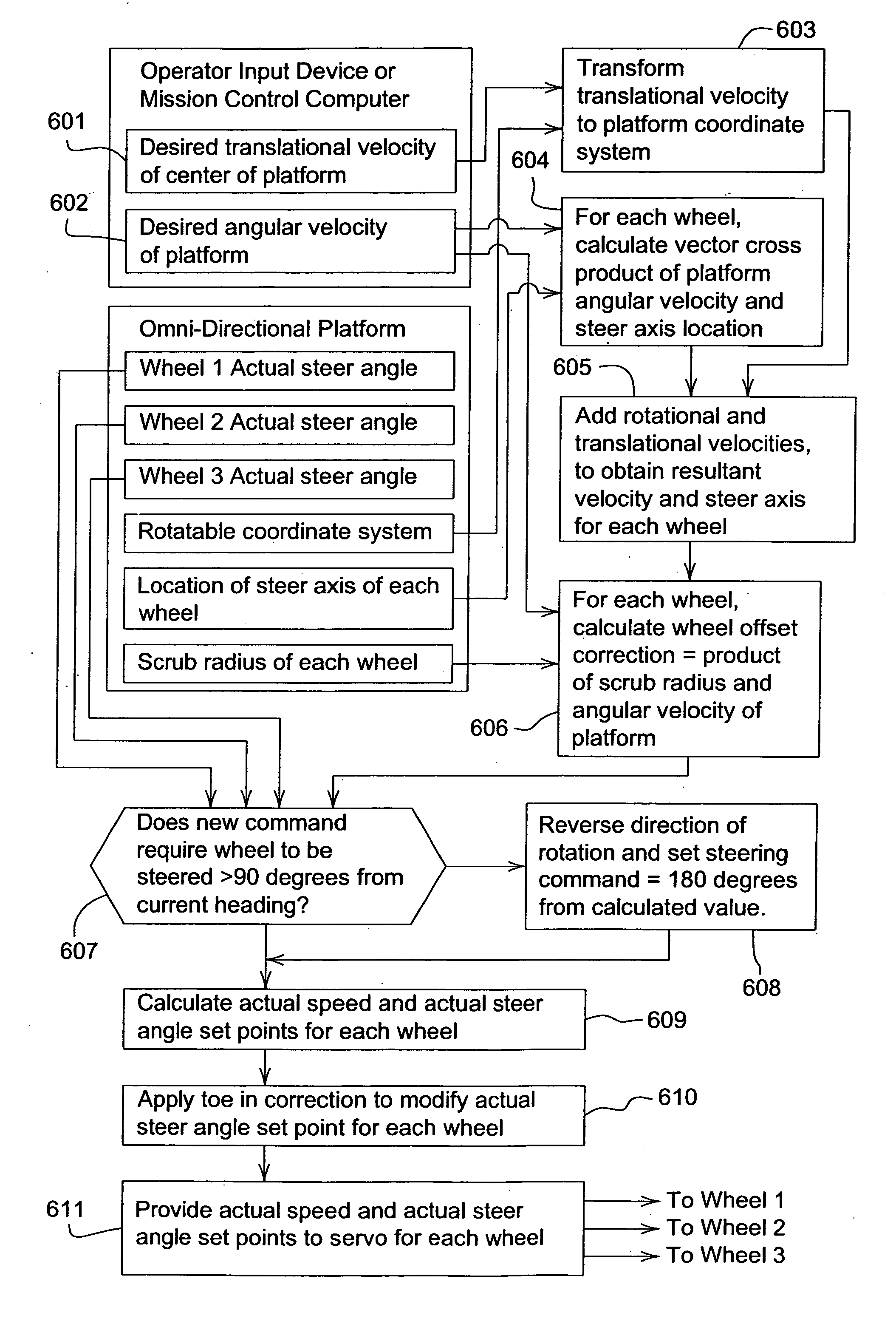
[0017] While this invention is susceptible of embodiment in many different forms, there are shown in the drawings, and will be described herein in detail, specific embodiments thereof with the understanding that the present disclosure is to be considered as an exemplification of the principles of the invention and is not intended to limit the invention to the specific embodiments illustrated.

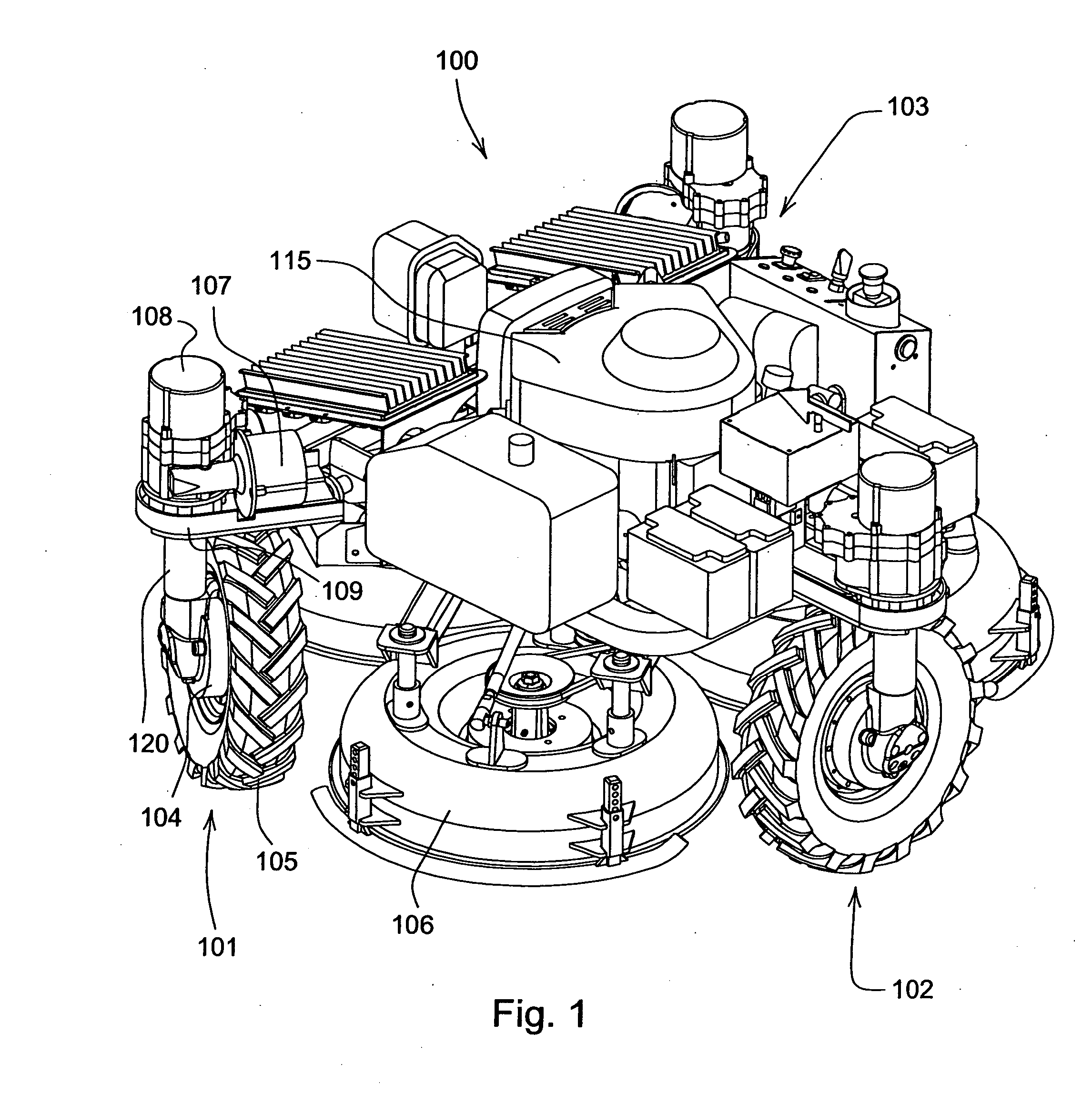
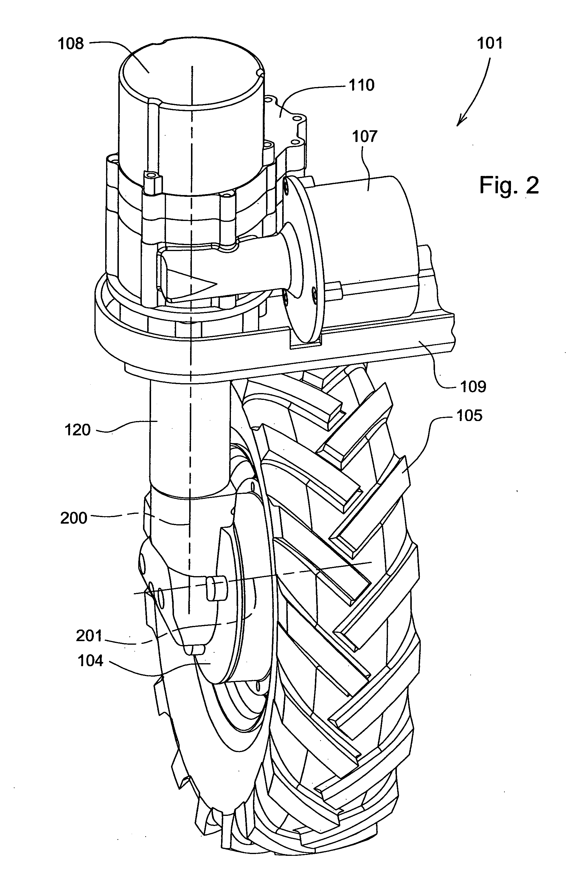
[0018] In one embodiment of the invention shown in FIG. 1, self-propelled mower 100 may include a plurality of traction wheels 101-03, a propulsion unit or engine 115, and at least one cutting deck 106 housing a blade for mowing grass. A tire 105 may be mounted on each wheel. The mower frame may be generally triangular and each wheel assembly may be positioned at or near the apex of sides of the triangle formed by the frame, although other shapes of the frame are possible and fall within the scope of the invention. Each wheel assembly may be positioned approximately equidistant on a radius abou...


PUM


Abstract

Steering logic for a self-propelled vehicle having a plurality of wheels includes the steps of receiving translational velocity and angular velocity commands, determining the resultant velocity and steer angle of each wheel, and determining the wheel offset correction for each wheel based on the scrub radius of each wheel and the angular velocity command.

Description

TECHNICAL FIELD OF THE INVENTION [0001] The invention relates to self-propelled vehicles, and particularly to steering mechanisms for self-propelled mowers. BACKGROUND OF THE INVENTION [0002] Examples of self-propelled mowers are shown in U.S. Pat. Nos. 7,024,842 and 7,024,843 assigned to Deere & Company of Moline, Ill. The self-propelled mower frame supports wheel assemblies, a propulsion unit, and one or more mowing decks. Each wheel assembly may be associated with a corresponding wheel, electrical steering motor, and electrical drive motor. A controller controls a steering direction of orientation of the corresponding wheel via application of electrical energy to the corresponding drive motor consistent with maneuverable movement of the mower. The propulsion unit is capable of rotating at least one cutting blade housed under a mower deck. Self-propelled mowers may be riderless, or may provide an operator station on the vehicle platform. [0003] Each wheel assembly may include a sp...

Claims


Application Information

Patent Timeline
IPC IPC(8): B62D6/00G06F17/00
CPCA01D34/008B62D11/001B62D7/1509B62D7/026
Inventor ROMIG, BERNARD EDWIN
Owner DEERE & CO
Why Eureka
Try Eureka