
Mechanical lubricating oil control safety valve assembly

The technology of one type lubricating oil and safety valve, applied in the field of high-pressure common rail fuel system, can solve the problems of lubricating oil protection function failure, cost reduction, engine friction failure, etc., to reduce the difficulty of seat surface processing, save materials, avoid The effect of pulling the cylinder and biting the card

Active Publication Date: 2021-03-26
CHONGQING HONGJIANG MACHINERY
View PDF14 Cites 0 Cited by
  • Summary
  • Abstract
  • Description
  • Claims
  • Application Information

AI Technical Summary

Problems solved by technology

[0003] The purpose of the present invention is to provide a mechanical lubricating oil control safety valve assembly, which integrates the lubricating oil safety valve and the rail pressure limiting valve, and solves the failure of the lubricating oil protection function caused by the failure of the program circuit, so that the engine friction caused by the oil cut-off The problem of failure, and at the same time meet the demand of the high-pressure common rail system for the rail pressure limiting valve, and reduce the cost

Method used


Image

  • Mechanical lubricating oil control safety valve assembly
  • Mechanical lubricating oil control safety valve assembly
  • Mechanical lubricating oil control safety valve assembly

Examples


Embodiment Construction

[0033] The present invention will be described in detail below in conjunction with the accompanying drawings.

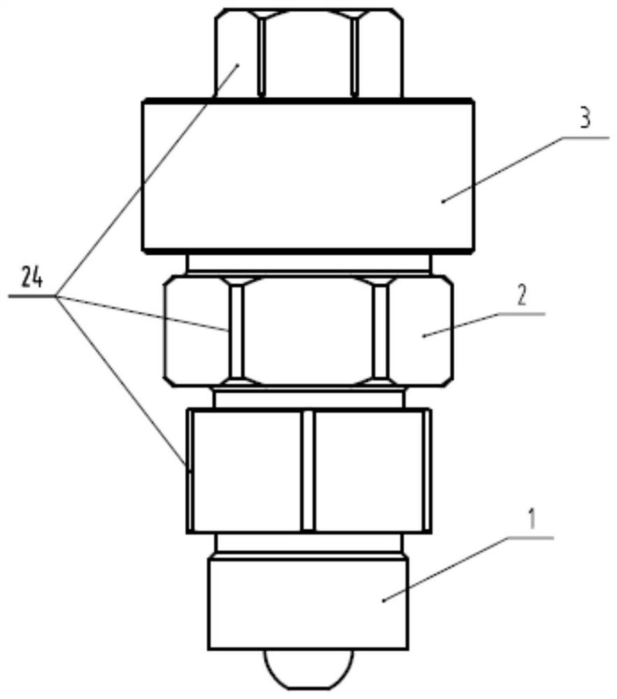
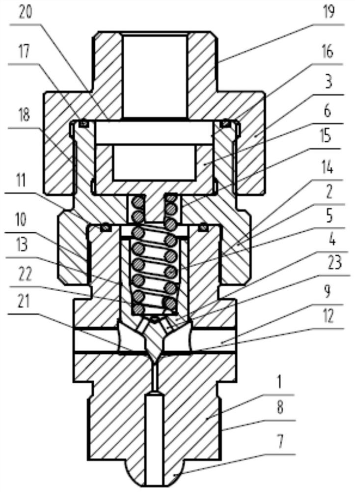
[0034] This embodiment provides a mechanical lubricating oil control safety valve assembly, whose function is to release the high-pressure common rail pressure when the oil pressure drops, so that the fuel injector stops spraying because the pressure is lower than the opening pressure, and then the engine stops. Prevent lubrication failure problems such as bearing bush holding the shaft and piston scuffing caused by the system running without oil. When the lubricating oil pressure is normal, if the fuel pressure in the high-pressure common rail exceeds the standard, the valve will open to release part of the pressure, so that the system can operate at low working conditions under part of the pressure.

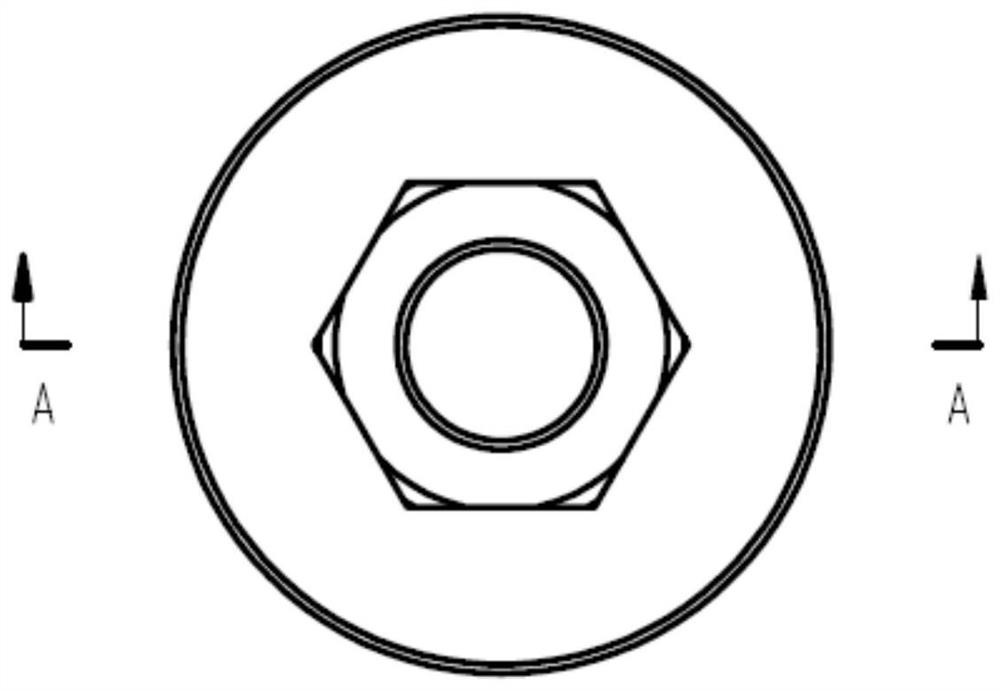
[0035] Such as Figure 1 to Figure 4 The mechanical lubricating oil control safety valve assembly shown is composed of a lower joint 1, a valve body 2, an upper join...


PUM


Abstract

The invention discloses a mechanical lubricating oil control safety valve assembly which comprises a lower connector, a valve body, an upper connector, a valve element, a spring and a control piston.The lower end part of the lower connector is a ball head, threads are arranged above the ball head and at the upper end part of the lower connector; a transverse through threaded hole is formed in themiddle of the lower connector and is an oil outflow hole; a sealing ring groove is formed in the upper end surface, and an oil passage is formed in the center of the lower connector in a penetratingmode; a through hole is formed in the center of the valve body in a penetrating mode; a lower hole is a threaded hole and is connected with the lower connector; an upper hole is a guide hole, and a sealing ring groove is formed in the upper end face; the oil passage is formed in center of the upper connector in a penetrating mode; the upper and lower holes are both threaded holes; the lower hole is connected with the valve body; the upper hole is connected with a lubricating oil pipe; a cone body is at the lower end part of the valve element and is placed on the lower connector, and the upperend part is provided with an inner hole for placing the spring; and the control piston is placed on the spring. By the mechanical lubricating oil control safety valve assembly, whether a system operates or not can be controlled according to the lubricating oil pressure, and the problem of friction failure, caused by insufficient lubricating oil, of bearing bush journal sticking, piston cylinder score and the like when the lubricating oil pressure is too low is solved.

Description

technical field [0001] The invention belongs to the technical field of high-pressure common rail fuel systems, and in particular relates to lubricating oil control safety technology. Background technique [0002] The electronically controlled common rail fuel system can realize precise control of fuel injection timing and cycle fuel injection volume, and is one of the effective means for high-power marine diesel engines to achieve high fuel economy and low harmful emissions. Due to the high power, the electronically controlled common rail fuel system has high rail pressure and large impact, which has great requirements on the stability of lubricating oil. When the lubricating oil pressure is low or the lubricating oil leaks, if the system is still running, it will cause problems such as bearing pads clinging to the shaft, pistons and cylinders. The existing circumvention method is to use electronic control to automatically stop when the lubricating oil pressure is low, but ...

Claims


Application Information

Patent Timeline
Patent Type & Authority Applications(China)
IPC IPC(8): F16K17/06F16K17/19F16K17/30F16K17/32F16K27/02F16K31/122F01M1/24
CPCF16K17/065F16K17/0466F16K17/048F16K17/19F16K17/30F16K17/32F16K27/0254F16K31/1221F01M1/24
Inventor 侯旭洪张鹏高浪扈爽包涛张朦朦罗小华熊博熠
Owner CHONGQING HONGJIANG MACHINERY
Learn More