
Method and arrangement in a communication system

Inactive Publication Date: 2007-11-08
GOOGLE LLC
View PDF14 Cites 45 Cited by
  • Summary
  • Abstract
  • Description
  • Claims
  • Application Information

AI Technical Summary

Benefits of technology

[0032] Another object is to provide a better quality, as interpreted by a listener, of the play back of the digitized sound signal received as data packets, in comparison with the quality of such play back accomplished with the presently known techniques.
[0038] Preferably, whenever a number of consecutive signal frames are available at the decoder, where the number of frames is time dependent, and based on the real-time statistics from the jitter buffer, a compression of two or more frames is attempted. This may or may not lead to a compressed signal frame that is shorter than the sum of the lengths of the signal frames input to the compression. The difference in length may be a fractional number of samples and is dependent on signal fitting of the actual signal frames. If the signal fitting cannot produce a compressed signal frame with smooth transitions, as defined by a threshold in e.g. a correlation measure or a vector matching, the signal frames are left unchanged. This threshold is advantageously adapted over time to allow for a less critical criterion for the compression the closer the jitter buffer is to overflow. Moreover, the threshold can vary in dependence on a classification of the signal frames. For speech, signal classes with different thresholds for compression would typically be: voiced, unvoiced, transition, and silence. This setup allows for some signal classes to be compressed only when the jitter buffer is very close to overflow, whereas other signal classes are compressed even at normal operation conditions for the jitter buffer leading to a reduction of the delay of playback.
[0045] The iterated vector matching for the frame expansion in accordance with the present invention can be seen as an application of oscillator modeling. In this respect, the invention introduces four new concepts to oscillator modeling. Each of these concepts makes a refinement of the oscillator modeling, and each concept improves the performance of the combined timing recovery and lost frame substitution in accordance with the invention. Furthermore, each concept may be exploited separately, or in combination with the others. The concepts are as follows:
[0049] Periodicity of the iterated frame expansion is avoided by only using the same segment once for the expansion of a frame.
[0052] According to one embodiment, when merging two segments by overlap-add, the segment latest in time is preferably time-shifted with a number, or fractional number, of samples, thus optimising a correlation or a vector matching criterion for the overlapping part of the two segments. Alternatively, merging can be made by replacement of the codebook in an oscillator model. Both of these merging alternatives, when applied in a lost frame substitution situation, rely on the presence of an efficient timing recovery, which, as described previously is included in the inventive method of the present invention.
[0053] According to another embodiment, the merging can advantageously optimize a correlation or a vector matching criterion when the segment latest in time is multiplied by a gain, which gain is a free parameter in the optimization. From there, a smooth transition back to unity gain can be obtained over the remaining part of the trailing segment or over the following signal frames.

Problems solved by technology

In packet switched data networks, such as the Internet, the arrival time of data packets is subject to significant delay jitter.
Moreover, data packets can be lost in the transmission or deliberately discarded by the network in order to resolve congestion problems.
In this case, a transmission protocol with hand shaking and retransmission is most often not a feasible solution to ensure signal frames to be available for continued playback.
Furthermore, delay jitter is a source of problems for these signals: if the delay of a data packet results in it arriving too late for continued playback of consecutive signal frames, then problems arise that are similar to those that occur when the data packet was lost.
In a system that does not transmit data packets during silence, the jitter-buffer will empty as a natural consequence, and a sufficient buffering delay needs to be introduced at the beginning of each new talk spurt.
At a sudden increase of the transmission delay, there is the risk that an underflow of the jitter buffer occurs.
That is, no data packets are available in the jitter buffer at the required time of decoding to yield the signal frame for continued playback.
A sudden decrease of the transmission delay may cause an overflow of the jitter buffer.
Apart from implementation specific problems related to the device having sufficient capacity to store the additional packets, this situation is an indication that the system introduces excessive delay of the playback.
In addition to delay jitter in the transmission, also differences between clocks in the transmitting and receiving devices may cause buffer under- or overflow.
No signal fitting or estimation optimization, such as target matching or correlation maximization, is exploited in these methods.

Method used


Image

  • Method and arrangement in a communication system
  • Method and arrangement in a communication system
  • Method and arrangement in a communication system

Examples


Embodiment Construction

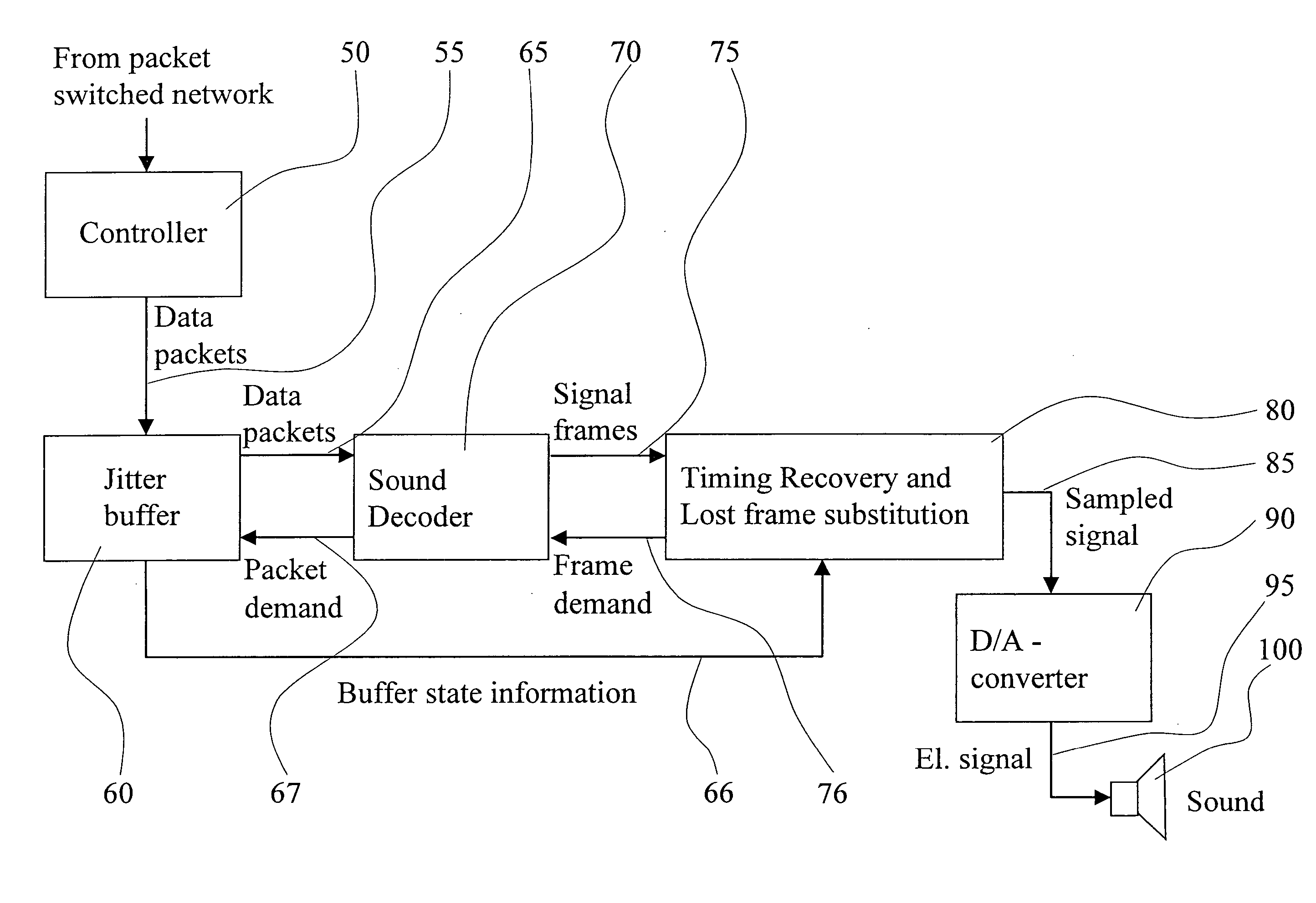
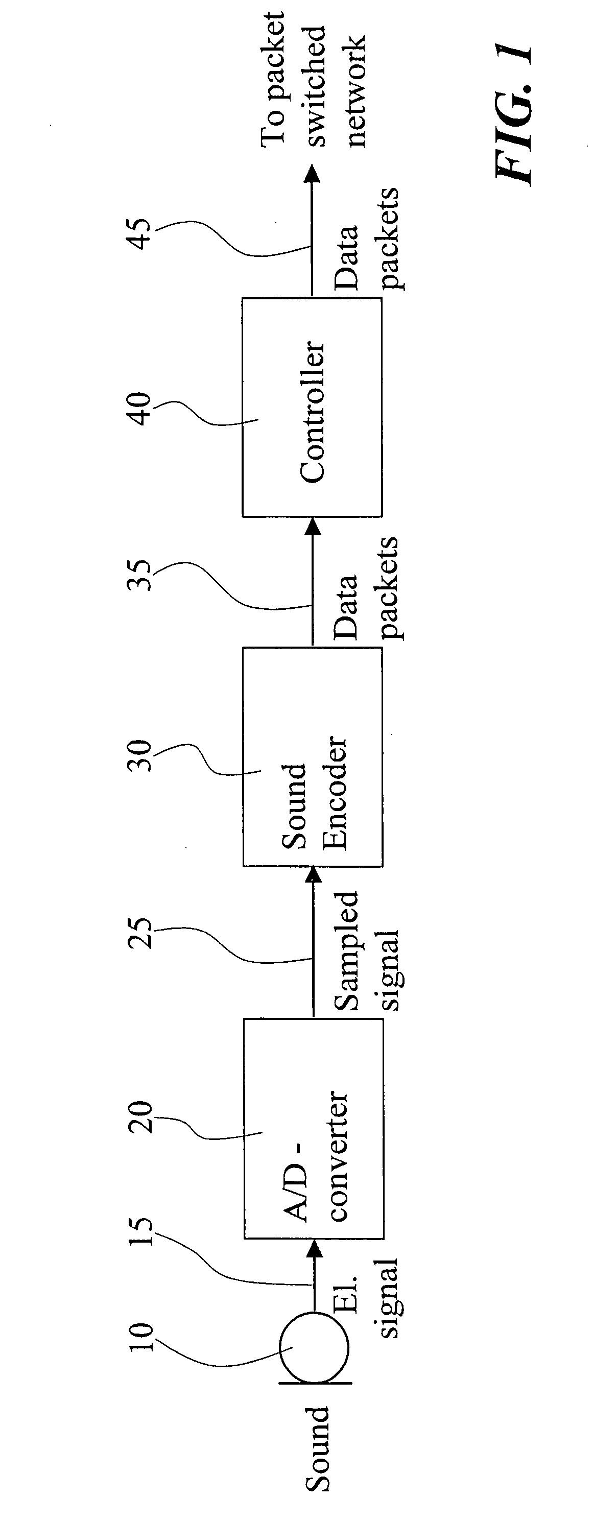
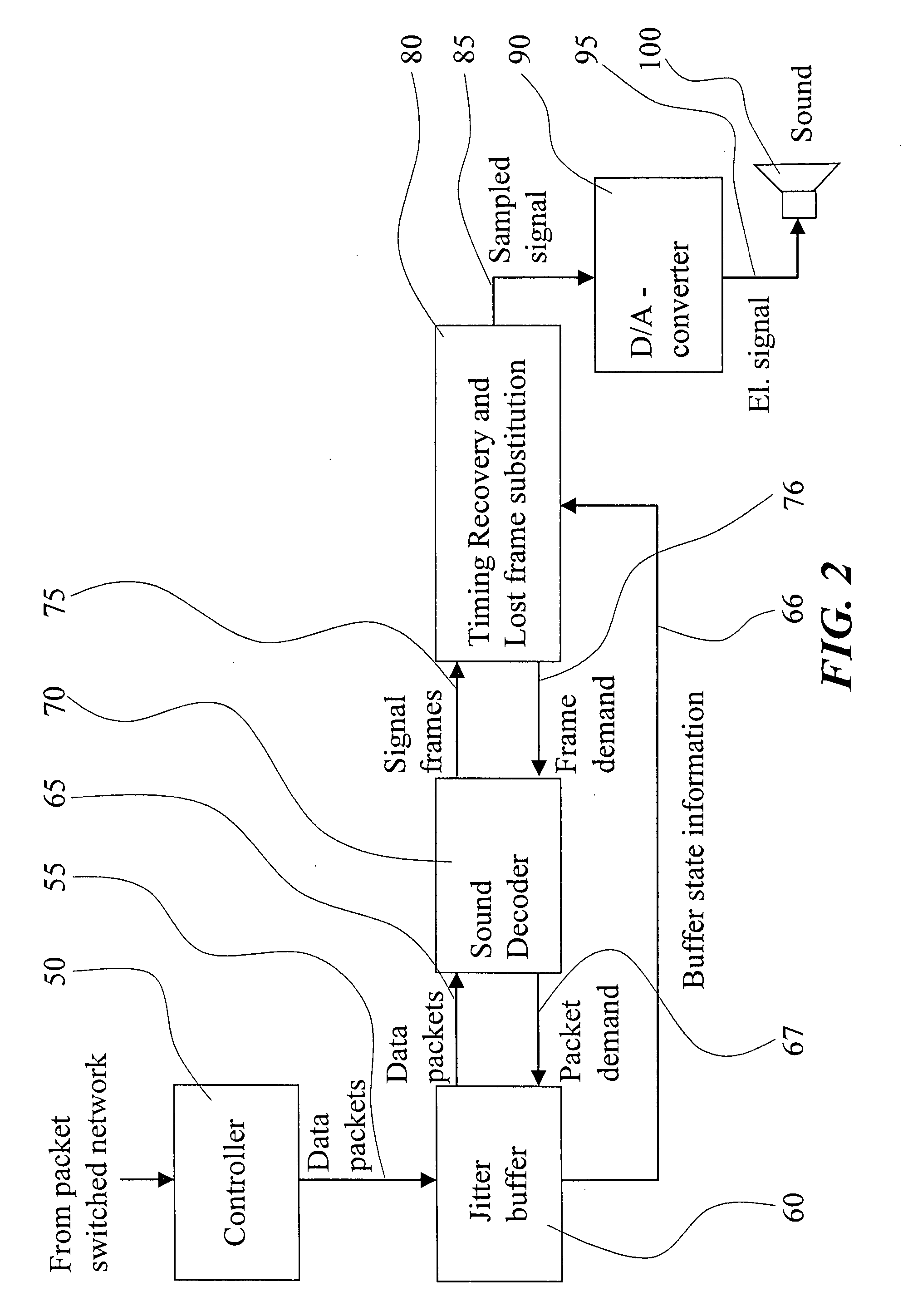
[0068]FIG. 1 is a block diagram of the transmitting part of a system for transmission of sound over a packet switched network. The sound is picked up by a microphone 10 to produce an electric signal 15, which is sampled and quantized into digital format by an A / D converter 20. The sample rate of the sound signal is a rate that is adequate for the bandwidth of the signal and is typically 8, or 16 kHz for speech signals and 32, 44.1 or 48 kHz for audio signals. The quantization accuracy of the digital representation is an accuracy that is adequate for the desired quality of the transmission, and is typically 7 or 8 bit A- or μ-law quantization, or, 13 or 16 bit uniform quantization. Alternatively, the A / D converter 20 is of the oversampled differential quantization type. The sampled signal 25 is input to a sound encoder 30. The sound encoder 30 produces data packets 35 with fixed or variable rate and with fixed or variable size. These data packets contain sufficient information for an...


PUM


Abstract

The present invention relates to the decoding / playback part of received sound data packets in systems for transmission of sound over packet switched networks. According to the invention, the lengths of received signal frames are manipulated by performing time expansion or time compression of one or more signal frames at time varying intervals and with time varying lengths of the expansion or the compression, said intervals and said lengths being determined so as to maintain a continuous flow of signal samples to be played back.

Description

TECHNICAL FIELD OF THE INVENTION [0001] The present invention is generally related to systems for transmission of sound over packet switched networks, and more specifically to the decoding / playback part of received sound data packets in such systems. TECHNICAL BACKGROUND AND PRIOR ART [0002] In packet switched data networks, such as the Internet, the arrival time of data packets is subject to significant delay jitter. Moreover, data packets can be lost in the transmission or deliberately discarded by the network in order to resolve congestion problems. For data transmissions without strict requirements on the transmission time, an error-free transmission can be established with a transmission protocol that uses hand shaking and retransmission. [0003] When sound signals such as speech or audio are transmitted over a packet switched network, signal frames, i.e. consecutive sets of signal samples, are encoded to result in data packets, each data packet corresponding to one or multiple ...

Claims


Application Information

Patent Timeline
IPC IPC(8): G10L21/00H04L12/64
CPCH04L12/64
Inventor ANDRSEN, SOREN V.KLEIJN, WILLEM B.SORQVIST, PATRIK
Owner GOOGLE LLC
Learn More