Unlock instant, AI-driven research and patent intelligence for your innovation.

Inertial force sensor

a sensor and inertial force technology, applied in the direction of acceleration measurement using interia force, acceleration measurement in multiple dimensions, instruments, etc., can solve the problems of high sensitivity of transducers, increased cost, and easy meeting of reproducibility limitations with such techniques, so as to reduce oscillations in position

Active Publication Date: 2007-11-15
PIXART IMAGING INC
View PDF10 Cites 14 Cited by
  • Summary
  • Abstract
  • Description
  • Claims
  • Application Information

AI Technical Summary

Benefits of technology

[0009] The present invention includes a sensor having a mass that moves relative to a structure. A spring mechanism applies a restoring force to the mass when the mass moves from an equilibrium position with respect to the structure. A first code scale is attached to the mass and viewed by a first imaging system that is fixed with respect to the structure. The first imaging system forms images of the first code scale that are used by a controller to provide an indication of the relative position of the

Problems solved by technology

If a simple threshold measurement is all that is required, the reproducibility limitations can be easily met with such techniques.
However, if a more accurate analog measurement is needed, the device may need to be individually calibrated leading to increased cost.
In addition, the amount of motion that must be sensed in these miniature devices requires a transducer that has high sensitivity, particularly if an analog measurement of the displacement is needed.
The cost of such transducers can limit the applications in which such analog sensors can be utilized.
In addition, these sensors must often operate in a hostile environment in which the temperature varies over a large range and in which dirt and other contamination can buildup leading to device failure.
Furthermore, these sensors typically require one transducer per degree of freedom.
The additional transducers increase the cost of the sensor.
Finally, these sensors are subject to oscillations resulting from resonances in the spring-mass system.
The damping mechanism must not interfere with the transducer mechanism, and hence, there are constraints on the damping mechanism that further increase the cost of the sensor.

Method used


Image

  • Inertial force sensor
  • Inertial force sensor
  • Inertial force sensor

Examples


Embodiment Construction

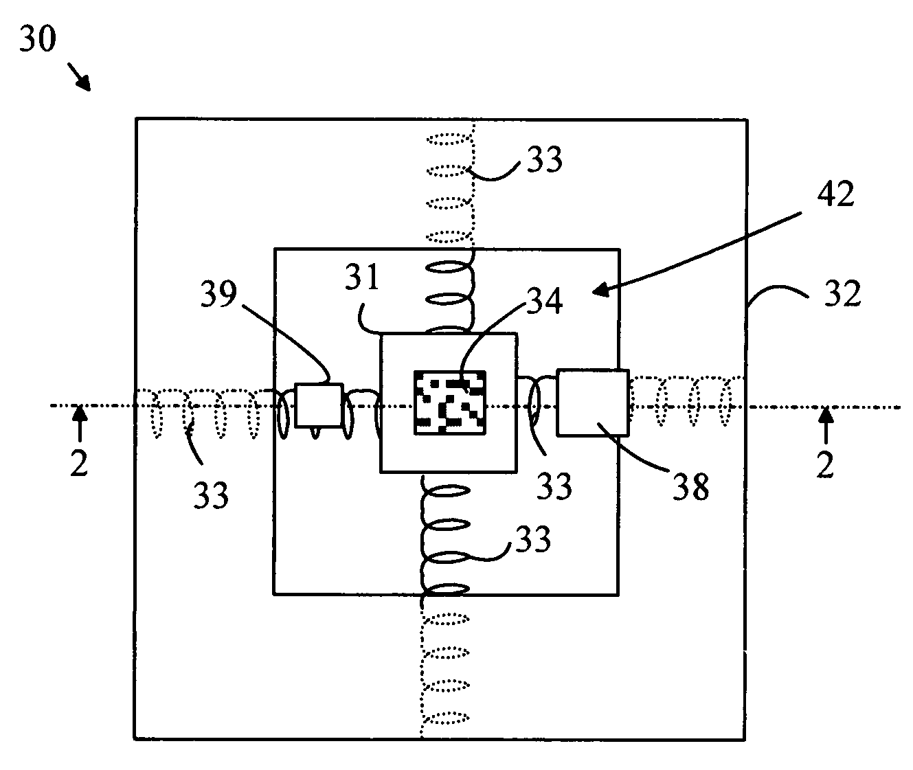
[0022] The manner in which the present invention provides its advantages can be more easily understood with reference to FIGS. 1-2, which illustrate a two-dimensional inertial force sensor according to one embodiment of the present invention. FIG. 1 is a top view of sensor 30, and FIG. 2 is a cross-sectional view through line 2-2 shown in FIG. 1. Sensor 30 includes a mass 31 that is connected to a structure 32 by a plurality of springs 33. Mass 31 moves with respect to structure 32 when a force is applied to either mass 31 or structure 32. In the absence of such a force, mass 31 is maintained at a predetermined position relative to structure 32 by springs 33. Mass 31 includes a scale 34 that moves with mass 31 and includes a pattern that is viewed by an imaging system 38 that is fixed with respect to structure 32. Imaging system 38 includes an image sensor 35 that forms an image of a portion of scale 34. By comparing the portion of scale 34 that is currently within a predetermined f...


PUM


Abstract

A sensor having a mass that moves relative to a structure is disclosed. A spring mechanism applies a restoring force to the mass when the mass moves from an equilibrium position with respect to the structure. A first code scale is attached to the mass and viewed by a first imaging system that is fixed with respect to the structure. The first imaging system forms images of the first code scale that are used by a controller to provide an indication of the relative position of the mass with respect to the structure. The mass can be located in a sealed chamber in the structure that has a transparent liquid through which the mass moves. The first imaging can view the first code scale from outside the chamber through a transparent window in the chamber.

Description

BACKGROUND OF THE INVENTION [0001] Inertial force sensors are used in numerous consumer products. For example, various occupant protection systems in automobiles utilize such sensors to trigger actions designed to protect the vehicle occupant when the automobile is involved in a collision or the system senses that a collision is imminent. Such systems are used to actuate air bags in the event of a collision and to pretension seatbelts when sensors indicate that a collision is about to occur. [0002] These sensors typically utilize a weight and spring arrangement in which a moveable weight is fixed to a stationary component by a spring. When the apparatus is accelerated or decelerated, the weight moves relative to the stationary component. Such sensors typically include a transducer that converts the position of the weight relative to the fixed component, or the rate of change in that position, into an electrical signal representing the displacement or rate of change of the position, ...

Claims


Application Information

Patent Timeline
IPC IPC(8): G01P15/00
CPCG01P15/0888G01P15/18G01P15/093
Inventor MURELITHARAN, MUNIANDY
Owner PIXART IMAGING INC
Features
  • R&D
  • Intellectual Property
  • Life Sciences
  • Materials
  • Tech Scout
  • Unparalleled Data Quality
  • Higher Quality Content
  • 60% Fewer Hallucinations
Learn More