Actuating Device with Rotary Switch

Active Publication Date: 2007-11-15
ZF FRIEDRICHSHAFEN AG
View PDF8 Cites 64 Cited by
  • Summary
  • Abstract
  • Description
  • Claims
  • Application Information

AI Technical Summary

Benefits of technology

[0012] Against this background, the object of the present invention is to provide a means for the by-wire actuation of a technical system, for example, a speed-change gear, with which the drawbacks of the state of the art can be overcome. In particular, the actuating device shall increase the freedom in designing and arranging the actuating element, and the actuating device shall at the same time also be intuitive and self-explanatory to the operator to the extent possible. One im

Problems solved by technology

For example, the type and the location of arrangement of the operating lever for a motor vehicle transmission are markedly limited because of the considerable space requirement of such gearshift levers and are limited essentially to the usual accommodation of the gearshift lever in the area of the center console or between the front seats of the motor vehicle.
This is accompanied by limitations in terms of design, and the freedom allowed to the vehicle designer is reduced essentially to the usual locations for mounting the gearshift lever.
The gearshift lever protruding from the center console is not infrequently also disadvantageous in terms of the freedom of motion for the vehicle occupants.
The classical gearshift or selector levels are also often disadvantageous with respect to safety on the motor vehicle.
For example, the clothing of the driver or front-seat passenger may get caught by the gearshift lever during motions and this may compromise the driver's attention to what is happening o

Method used


Image

  • Actuating Device with Rotary Switch
  • Actuating Device with Rotary Switch
  • Actuating Device with Rotary Switch

Examples


first embodiment

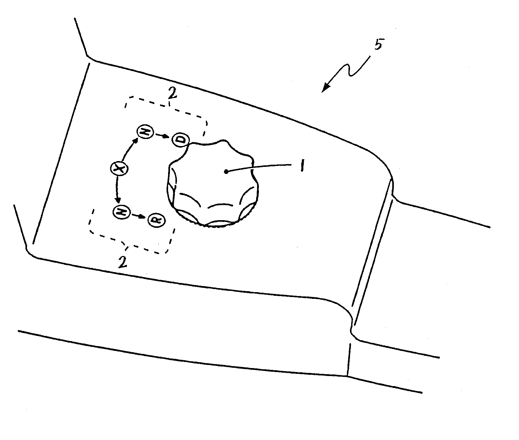
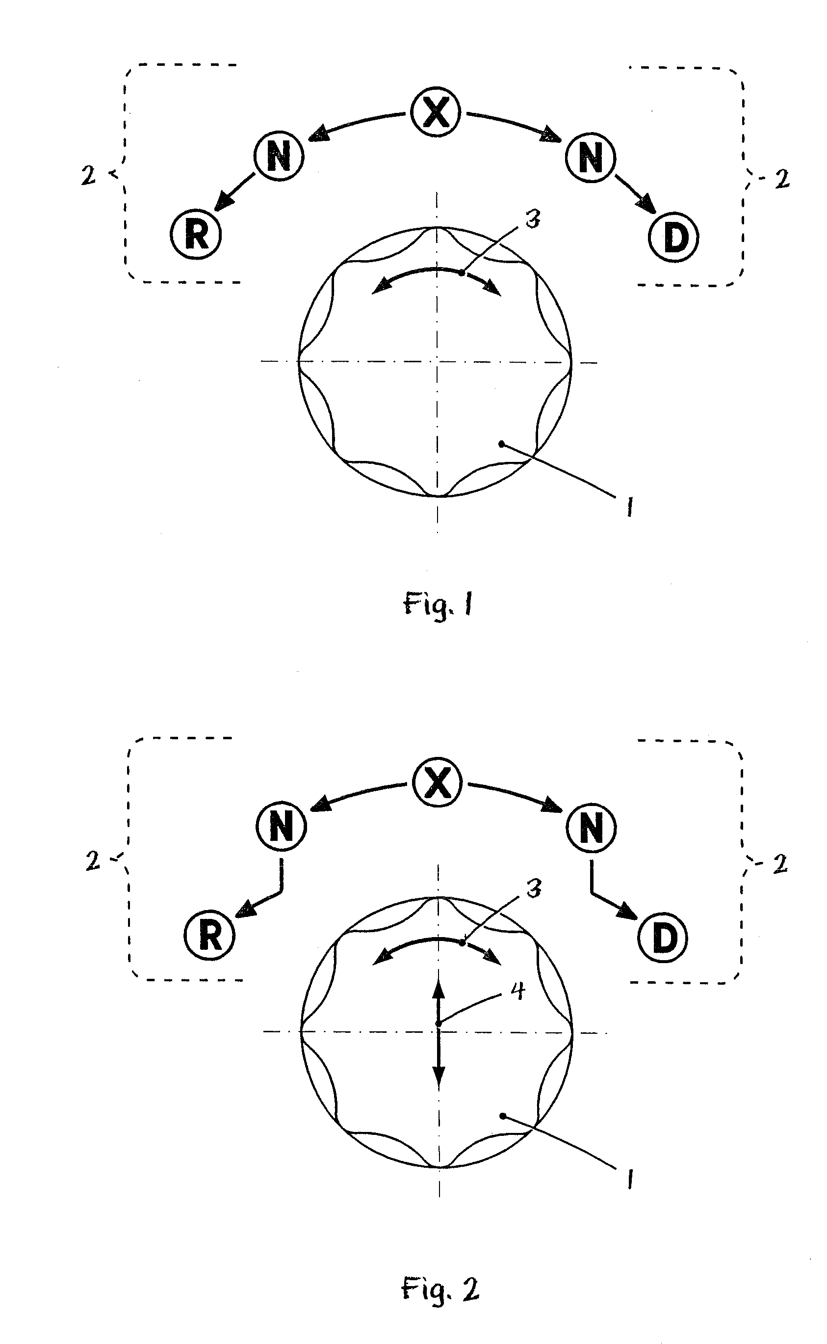
[0039] Referring to the drawings in particular, FIG. 1 shows a schematic view of the rotary switch 1 and the display means 2 of the actuating device according to the present invention. This embodiment is an actuating device for an automatic transmission of a vehicle.

[0040] It can be immediately recognized at first from the view in FIG. 1 that the rotary switch 1 can be turned to the left along its direction of rotary motion 3 in order to select the shifting states “N” or “R” starting from a starting position of the rotary switch 1, which is designated by “X” here, and that the rotary switch 1 can, furthermore, also be turned to the right along its direction of rotary motion 3 in order to select now the shifting state “N” or the shifting state “D.”

[0041] The actuating device is designed here according to the present invention such that the rotary switch 1 will again automatically assume the basic position at “X” after being released from each of the shift positions “N,”“R” and “D.”

[0...

second embodiment

[0045]FIG. 2 shows an actuating device for a vehicle transmission with a rotary switch 1. The embodiment according to FIG. 2 differs from the embodiment according to FIG. 1 especially in that the rotary switch 1 according to FIG. 2 can also be displaced, moreover, in a radial direction 4 or along the plane of the vehicle console (not shown), besides the rotary motion 3 about its axis. The blocking device of the actuating device according to FIG. 2 also differs in this connection from the blocking device of the actuating device according to FIG. 1.

[0046] The view in FIG. 2 can, furthermore, also be interpreted such that the rotary switch 1 according to FIG. 2 can also be pushed or pulled in the axial direction, in other words, displaced along its axis of rotation—instead of along the radial direction 4—besides the rotary motion 3 about its axis.

[0047] To engage one of the two gears “R” or “D” with the rotary switch 1 according to FIG. 2 starting from the starting position “X” or sta...

fourth embodiment

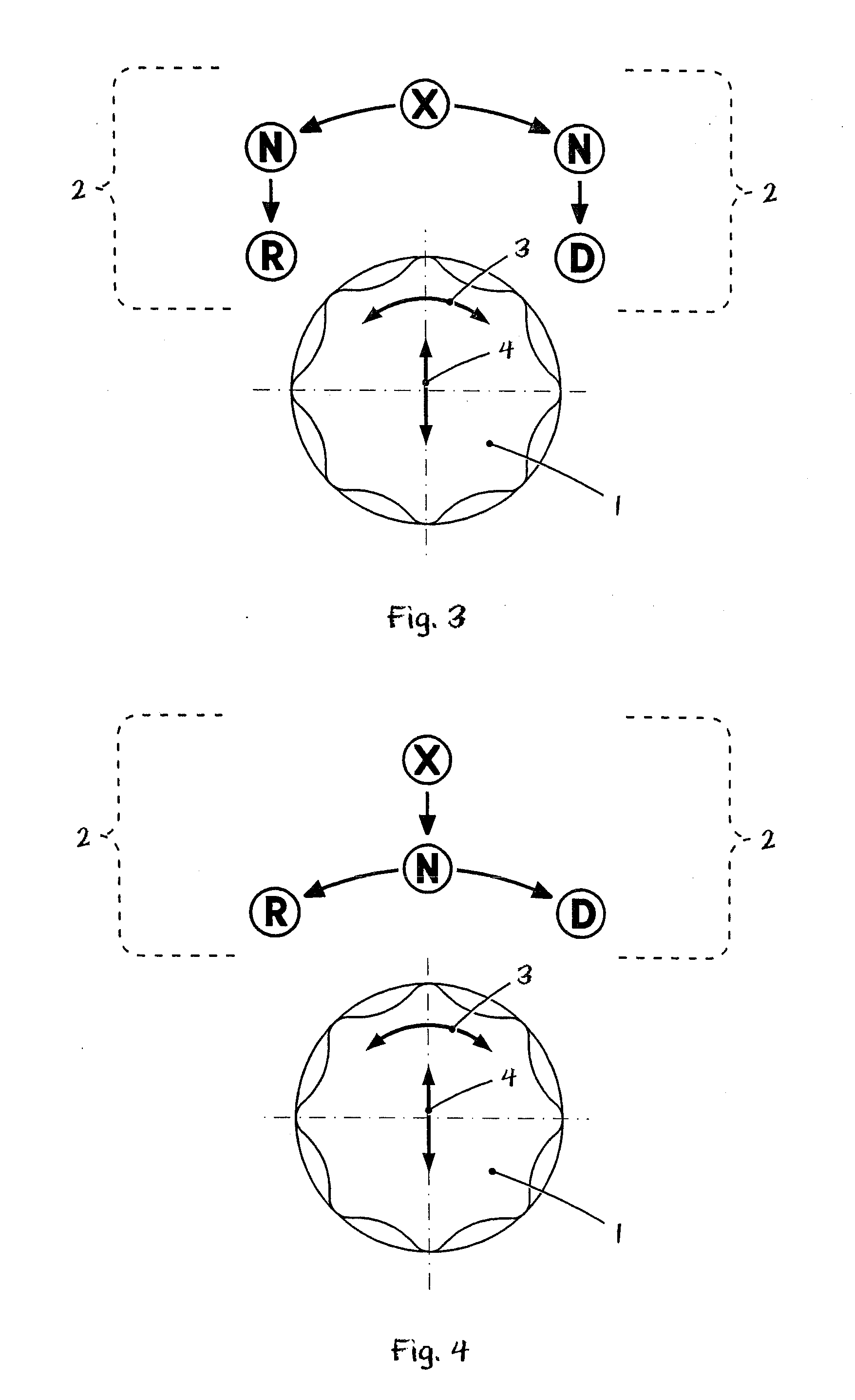
[0051] an actuating device for a vehicle transmission with a rotary switch is shown in FIG. 4. This embodiment differs from the preceding embodiments especially in that only one switching position of the rotary switch 1 is associated with the neutral position “N” of the vehicle transmission, as well as in that both the neutral position “N” of the vehicle transmission and the display of the instantaneously engaged gear “X” are associated with the initial rotation position of the rotary switch 1.

[0052] The selection of one of the gears “R” or “D” thus takes place in the case of the embodiment according to FIG. 4 such that the rotary switch 1 is first displaced starting from its starting position or basic position linearly downward relative to the drawing along its direction of radial motion 4 (or, for example, it is pushed in along its axial direction in another embodiment). As a consequence of the blocking means of the actuating device, which comprises a shift gate, it is subsequentl...


PUM


Abstract

An actuating device is provided that includes an actuating element (1) with at least three switching positions. The actuating device (1) can be deflected starting from its basic positions at least in one direction into an intermediate switching position for selecting an operating state of the technical system. For selecting at least one other operating state of the technical system, the actuating element (1) can be deflected, starting from an intermediate switching position, into at least one other switching position that is located farther away from the basic position. The undesired jumping of the actuating element over intermediate switching positions, during switching, is effectively prevented from occurring. An intuitively detectable tactile feedback of the switching state of the actuating element or of the state of the system is provided.

Description

CROSS REFERENCE TO RELATED APPLICATIONS [0001] This application is a United States National Phase application of International Application PCT / DE2005 / 002008 and claims the benefit of priority under 35 U.S.C. § 119 of German Patent Application DE 10 2004 054 264.3 filed Nov. 9, 2004, the entire contents of which are incorporated herein by reference.FIELD OF THE INVENTION [0002] The present invention pertains to a means for actuating a technical system, especially for a shift-by-wire speed-change gear, in which the actuating device comprises an actuating element with at least three shift positions including a basic position, wherein the actuating element can be deflected from the basic position at least in one direction into an intermediate switching position and can be deflected from the intermediate switching position into at least one other switching position located farther away from the basic position than the intermediate switching position. BACKGROUND OF THE INVENTION [0003] Th...

Claims


Application Information

Patent Timeline
IPC IPC(8): G05G1/08
CPCB60K37/06B60K2350/102F16H59/08F16H61/22F16H2059/0295G05G1/087Y10T74/20474G05G5/03G05G5/05G05G5/12G05G9/02F16H2059/081F16H2059/048G05G5/005B60K2370/126B60K2370/158
Inventor MEYER, JORGGIEFER, ANDREAS
Owner ZF FRIEDRICHSHAFEN AG
Why Eureka
Try Eureka