Capillary flow restrictor apparatus

a restrictor and capillary technology, applied in the direction of liquid degasification, positive displacement liquid engine, separation process, etc., can solve the problem of solvent vapor infiltrating the pump from the degassing vacuum chamber, affecting the accuracy and sensitivity of the results, and species can additionally produce unwanted changes or deterioration in the mobile phase itself, so as to facilitate the degassing operation and reduce the likelihood of becoming plugged , the effect of inhibiting the blockage of the ven

Active Publication Date: 2007-11-15
IDEX HEALTH & SCI
View PDF6 Cites 15 Cited by
  • Summary
  • Abstract
  • Description
  • Claims
  • Application Information

AI Technical Summary

Benefits of technology

[0020] By means of the present invention, dilution gas flow into targeted cavities of a pump utilized in combination with compression chamber vacuum degassing operations is facilitated without the drawbacks associated with porous frit flow restrictor mechanisms. Specifically, a continuous vent channel is provided that is defined by a continuous lumen within material that is resistant to corrosion from solvent vapors or other materials commonly present in liquid degassing operations. Moreover, the continuous vent channel provides a minimum cross-sectional area that is sufficiently large to minimize the likelihood of becoming plugged as a result of infiltration of particulate debris.
[0021] In a particular embodiment, the vacuum degassing apparatus of the present invention is configured for degassing one or more liquids, with the apparatus including a vacuum chamber, a liquid conveyance member disposed in the vacuum chamber for transporting the one or more liquid between an inlet and an outlet of the vacuum chamber, and a pump that is adapted to operably evacuate the vacuum chamber. The pump preferably includes a pumping cavity that is vented through a continuous vent channel. In preferred embodiments, the vent channel is formed by the lumen of a capillary tube that is fabricated from a non-metal material such as glass. In addition, a filter may be disposed at an inlet of the vent channel to further inhibit blockage of the vent channel by particulate matter.
[0022] In another embodiment of the present invention, a pump for use in operably evacuating a chamber in a vacuum degassing apparatus includes one or more pumping cavities that are in fluid communication with the chamber, and a continuous vent channel that has an outlet disposed in fluid communication with a respective one of the one or more pumping cavities. The vent channel is specifically configured to provide dilution gas flow into the pumping cavity at a rate sufficient to prevent solvent condensation in the pumping cavity.

Problems solved by technology

A particular example of such an application is in the degassing of the mobile phase in a liquid chromatography system, where the presence of even small amounts of dissolved gases can interfere with the accuracy and sensitivity of the results obtained.
Moreover, if the dissolved species is chemically active, as in the case of oxygen and air, such species can additionally produce unwanted changes or deterioration in the mobile phase itself.
One issue that arises in the use of such pumps in vacuum degassing applications, however, is the presence of solvent vapor infiltrating the pump from the degassing vacuum chamber as a result of permeation of such solvent vapors through the semi-permeable membrane wall disposed in the chamber.
If the concentration of the solvent vapor reaches a critical level, solvent condensation may occur, leading to operational and durability problems of the pump.
For example, condensed solvent may cause a pump to “choke” and may also cause corrosion of metallic parts in the pump.
Under dynamic flow conditions, however, the amount of solvent permeating the membrane increases due to the introduction of entrained air into the chamber that reduces the solvent partial vapor pressure within the vacuum chamber.
Such sintered porous frits, however, present operational drawbacks and the potential for degradation over time.
Corrosion of such sintered porous frits manufactured from, for example, stainless steel, may cause significant and permanent changes in vent gas flow restriction.
Such changes may be difficult to track over time, and may therefore degrade the accuracy and efficiency of the vacuum degassing operations unbeknownst to the system operator.
Due to the small size of the frit pores, particles may become lodged within the pores, thereby blocking or reducing vent gas passage therethrough.
The small pore size can also lead to solvent vapor condensation within the pores, which can cause vent gas restriction and / or vapor condensation within the pumping cavities.
In addition, such sintered porous frits are relatively expensive.

Method used


Image

  • Capillary flow restrictor apparatus
  • Capillary flow restrictor apparatus
  • Capillary flow restrictor apparatus

Examples


Embodiment Construction

[0026] The objects and advantages enumerated above together with other objects, features, and advances represented by the present invention will now be presented in terms of detailed embodiments described with reference to the attached drawing figures which are intended to be representative of various possible configurations of the invention. Other embodiments and aspects of the invention are recognized as being within the grasp of those having ordinary skill in the art.

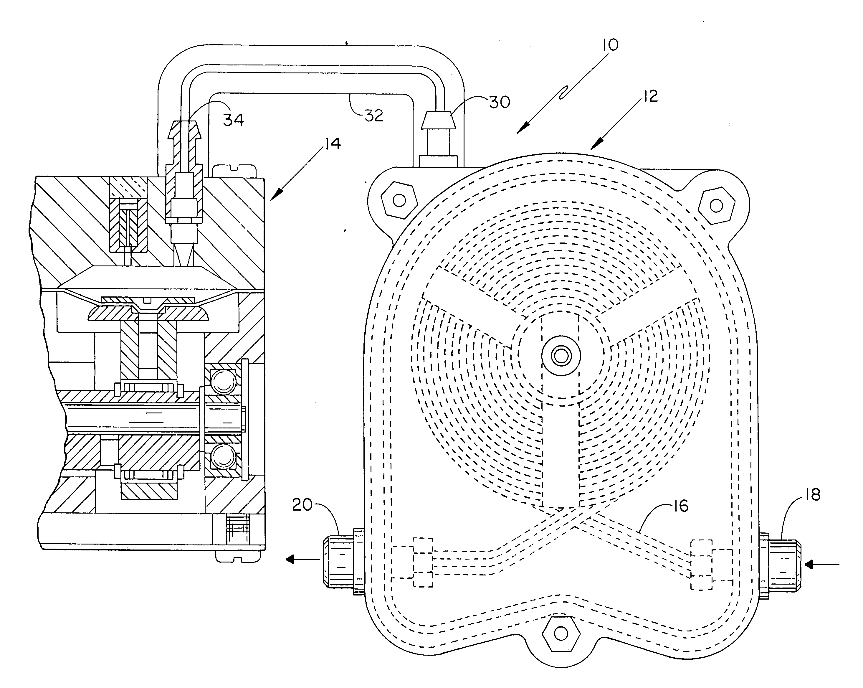
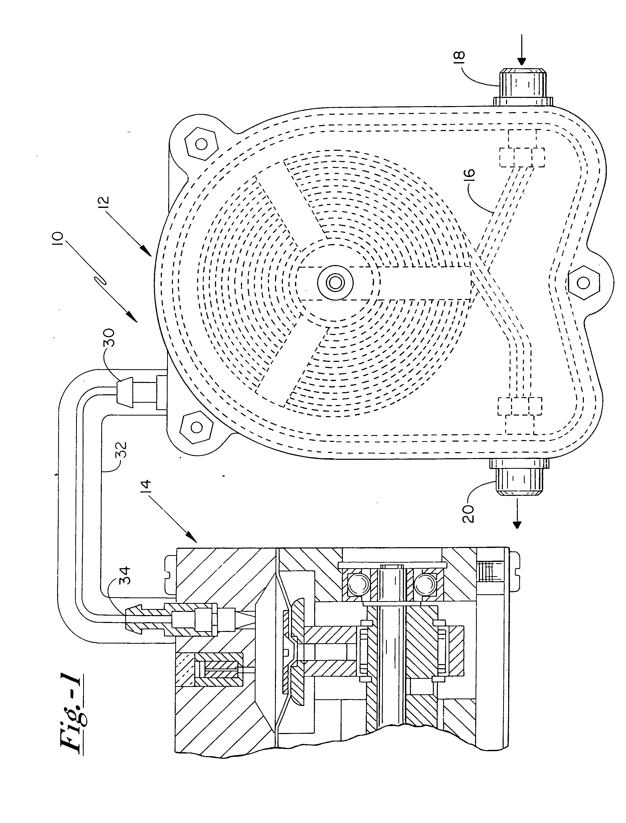
[0027] With reference now to the drawing figures, and first to FIG. 1, vacuum degassing apparatus 10 includes a vacuum chamber 12 and a pump 14 that is adapted to operably evacuate vacuum chamber 12. Pump 14 is preferably in fluid communication with vacuum chamber 12 through vacuum line 32 that connects chamber port 30 to pump inlet 34. A liquid conveyance member 16 is disposed in vacuum chamber 12, and is configured to operably transport one or more liquids between inlet 18 and outlet 20 of vacuum chamber 12.

[0028...


PUM

PropertyMeasurementUnit
cross-sectional diameteraaaaaaaaaa
pore sizeaaaaaaaaaa
pore sizesaaaaaaaaaa

Abstract

A pump for use in operably evacuating a chamber in a vacuum degassing apparatus includes one or more pumping cavities that are in fluid communication with the chamber, and a continuous vent channel that has an outlet disposed in fluid communication with a respective one of the one or more pumping cavities. The vent channel is configured to provide dilution gas flow into the pumping cavity of the pump at a rate sufficient to prevent solvent condensation in the pumping cavity during operation of the pump in liquid degassing applications.

Description

FIELD OF THE INVENTION [0001] The present invention relates to vacuum degassing systems generally, and more particularly to a vacuum degassing system that incorporates a pump for evacuating a chamber through which liquid to be degassed is conveyed, wherein the pump is vented through a continuous vent channel. BACKGROUND OF THE INVENTION [0002] Degassing of liquid solvents is an operation utilized in a variety of applications. A particular example of such an application is in the degassing of the mobile phase in a liquid chromatography system, where the presence of even small amounts of dissolved gases can interfere with the accuracy and sensitivity of the results obtained. Moreover, if the dissolved species is chemically active, as in the case of oxygen and air, such species can additionally produce unwanted changes or deterioration in the mobile phase itself. [0003] Techniques for degassing liquid materials have included heating or boiling the liquid to be degassed, exposing the ma...

Claims


Application Information

Patent Timeline
Patent Type & Authority Applications(United States)
IPC IPC(8): B01D19/00B01D53/22
CPCB01D19/0036B01D19/0063F04B25/005F04B45/047F04B37/20F04B45/043F04B37/14
Inventor GERNER, YURI
Owner IDEX HEALTH & SCI
Why Eureka
Try Eureka