
Paired-piston linear engine

a linear engine and piston technology, applied in the direction of positive displacement liquid engine, piston pump, machine/engine, etc., can solve the problems of difficult control of free pistons, complicated valving mechanism of current internal combustion engine, and complicated valving mechanism of available system

Active Publication Date: 2007-11-15
BENNION ROBERT F
View PDF9 Cites 29 Cited by
  • Summary
  • Abstract
  • Description
  • Claims
  • Application Information

AI Technical Summary

Benefits of technology

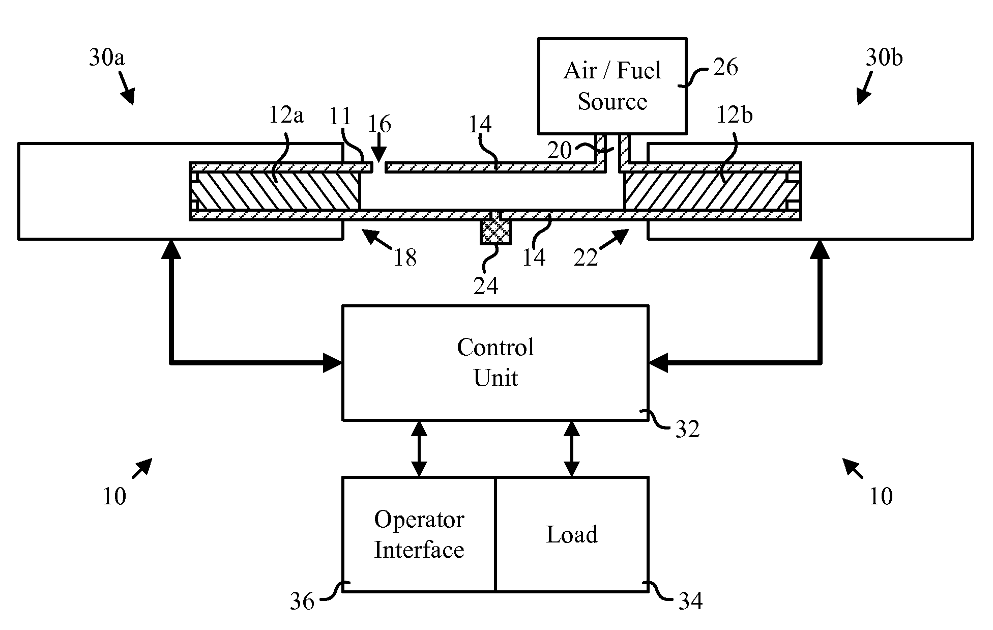
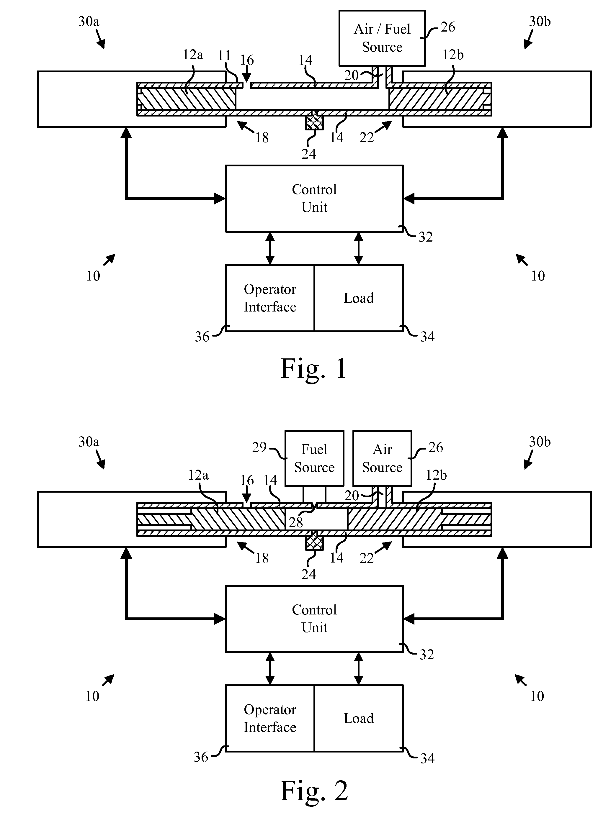
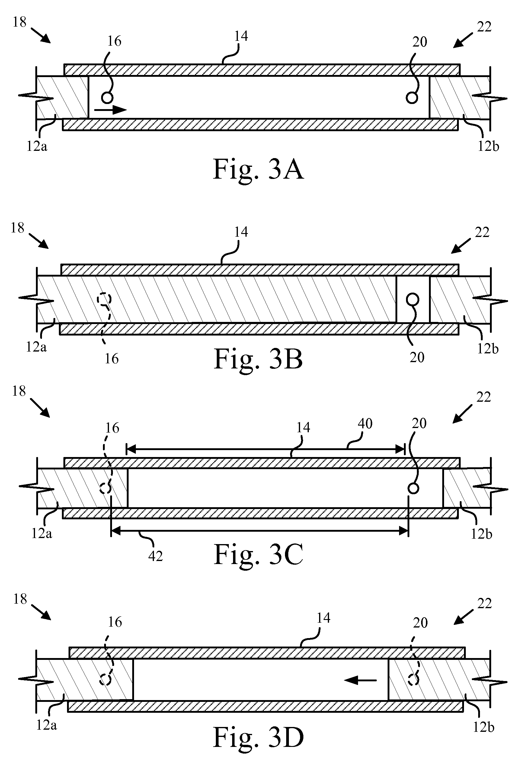
[0011]In one embodiment of the invention, a cylinder is provided having an exhaust port formed in the wall toward a first end and an intake port formed in the wall toward a second end. A first and second piston are placed into opposite ends of the cylinder and move therealong during a fluid handling process. During execution of the fluid handling processes, the pistons are moved over the intake and exhaust ports, sealing them off at appropriate times. Thus, the need for complicated valving mechanisms is eliminated.
[0013]In some embodiments, the first and second pistons are likewise coupled to generators, such that forced linear movement of the pistons during the combustion process generates electrical power. The generators and actuators may be separate units or may be an integrated device capable of performing both functions. In one embodiment, the functions of generator and actuator are performed by a linear switched reluctance motor. The linear switched reluctance motor is capable of converting the linear motion of the pistons into electrical power, thereby eliminating the need to convert the linear motion of the pistons to rotary motion.

Problems solved by technology

Current internal combustion engines further require complicated valving mechanisms in order to introduce fuel and air into the cylinder and to release exhaust gases.
However, free pistons are difficult to control in order to execute a multiple-phase combustion process.
Furthermore, currently available systems typically require complicated valving mechanisms similar to those in traditional internal combustion engines.
Accordingly, such systems have been cumbersome and unfeasible at small scales.

Method used


Image

  • Paired-piston linear engine
  • Paired-piston linear engine
  • Paired-piston linear engine

Examples


Embodiment Construction

[0027]Reference throughout this specification to “one embodiment,”“an embodiment,” or similar language means that a particular feature, structure, or characteristic described in connection with the embodiment is included in at least one embodiment of the present invention. Thus, appearances of the phrases “in one embodiment,”“in an embodiment,” and similar language throughout this specification may, but do not necessarily, all refer to the same embodiment.

[0028]Furthermore, the described features, advantages, and characteristics of the invention may be combined in any suitable manner in one or more embodiments. One skilled in the relevant art will recognize that the invention can be practiced without one or more of the specific features or advantages of a particular embodiment. In other instances, additional features and advantages may be recognized in certain embodiments that may not be present in all embodiments of the invention.

[0029]Referring to FIGS. 1 and 2, an engine 10 may i...


PUM


Abstract

A linear internal combustion engine is disclosed having a cylinder defining an intake port proximate a first end thereof and an exhaust port proximate a second end thereof. First and second pistons insert into opposite ends of the cylinder. Each piston is coupled to an actuator / generator, such as a linear switched reluctance motor. The actuator / generators are coupled to a control unit which controls the actuator / generators and extracts energy therefrom. The control unit causes the actuators to move the pistons through a fluid handling process, such as pumping, compression, or a four cycle combustion process coupled with a recovery phase. The pistons are positioned over the intake and output ports to seal them off at proper times during the fluid handling process.

Description

RELATED APPLICATIONS[0001]This application claims priority to U.S. Provisional Application No. 60 / 747,147 entitled “PAIR-PISTON LINEAR ENGINE” and filed on 12 May 2006 for Robert F. Bennion and Steven F. McDaniel which application is incorporated herein by reference.BACKGROUND OF THE INVENTION[0002]1. Field of the Invention[0003]This invention relates generally to internal combustion engines and more particularly to linear internal combustion engines.[0004]2. Description of the Related Art[0005]The vast majority of internal combustion engines currently in use are reciprocating engines in which a piston moves up and down within a cylinder. The linear motion of the piston is translated into rotary motion by a crankshaft connected to the piston by a piston rod. In a typical engine, due to the large forces involved, the coupling between the crankshaft and the piston rod and between the piston and the piston rod, is a simple journal bearing. Accordingly, significant friction is introduce...

Claims


Application Information

Patent Timeline
Patent Type & Authority Applications(United States)
IPC IPC(8): F02B25/08F02B75/28
CPCF02B25/08F02B71/00F04B17/05F04B7/04F04B3/00
Inventor BENNION, ROBERT F.
Owner BENNION ROBERT F
Learn More