Barking Device and Barking Tool

a barking device and tool technology, applied in the direction of turning tools, turning tools, tree debarking, etc., can solve the problems of time-consuming and labor-intensive to completely exchange barking tools, problems and drawbacks, and may have to change the contact angle of barking tools, so as to facilitate design and prevent rotation and displacement.

Active Publication Date: 2007-11-15
IGGESUND TOOLS
View PDF6 Cites 24 Cited by
  • Summary
  • Abstract
  • Description
  • Claims
  • Application Information

AI Technical Summary

Benefits of technology

[0025] According to the invention, one of the connecting means parts is formed as a sleeve-like nut with an internally threaded shank and a head. In a preferred embodiment, the length of the shank is adapted so that, in a tightened state when the barking tool is firmly connected to the barking arm, the shank extends through the entire part from which it is inserted, i.e. the barking tool in the shown preferred embodiment, and extends also a distance into the other part, i.e. the barking arm in the shown embodiment. As a result, the screw is relieved by only needing to absorb the tensile force which is required to safely connect the barking tool to the barking arm. However, the entire shear force and torque will be absorbed by the shank of the nut. Such an embodiment, however, is not absolutely necessary but the shank of the nut could be closed before it reaches through the entire part from which it is inserted (the barking tool in the shown embodiment). This is advantageous since an extra machining step for making a recess for the shank of the nut in the other part is avoided. Such a design is facilitated if the mounting surface and the seat surface are designed so as to obtain a clamping effect in mounting by the material of the barking tool and the barking arm being deformed when tightening the screw joint, as has been described above. This results in a clamping joint which contributes to holding the barking tool in a fixed position, which prevents the screw from being subjected to shear force and torque. In the shown preferred embodiment, the nut is closed at the end where the head is located, but it could also be open at both ends, like a tube.
[0026] In a tightened state with the mounting surface of the barking tool pressed against the seat surface of the barking arm, the head of one of the connecting means parts is positioned, in a manner preventing rotation and displacement, in the groove and / or the countersink round the same. The head as well as the countersink can be designed in various ways. As mentioned above, it is advantageous if the head fills out the entire countersink to prevent penetration of dirt, but the countersink need not necessarily have a uniform width round the groove so as to obtain an elongate shape as in the shown embodiment. Thus, it would also be possible to have a completely square countersink and head. It would also be possible to have a completely circular countersink and head if the associated shank is placed eccentrically to the head. For the purpose of preventing rotation, such a head and countersink could be supplemented, for instance, with some kind of projections and recesses in the case where the shank is centred on the head. Moreover the countersink need not be continuous along the entire circumference of the groove.
[0027] As mentioned above, there are two different ways of providing setting of the barking tool in different mounting positions, so that its front barking-edge-forming edge portion takes a different angle relative to the log surfaces that are to be barked, i.e. different degrees of aggressiveness. One way involves turning a displacement and rotation preventing head with an eccentrically arranged shank. In that case, the screw joint need not be completely released, but only to such an extent that the head can be raised from the countersink and turned. The other way involves exchanging the displacement and rotation preventing connecting means for one with a different eccentricity or no eccentricity at all. It is thus possible to rotatingly displace the barking tool to an arbitrary mounting position by a suitable design of the connecting means.

Problems solved by technology

Also when barking the same kind of tree species, the contact angle of the barking tool may have to be changed owing to a change in temperature, since, for instance, frozen bark is considerably more difficult to shear off than unfrozen bark.
The drawback in this case, however, is that several sets of barking tools must be available for one and the same barking machine, and it is also time-consuming to completely exchange the barking tools, which in some cases may have to be done several times a day.
However, there remain other problems and draw-backs.
In this construction however, the barking tool is not locked in the longitudinal direction of the ridge and the grooves, but these forces are fully absorbed by the shank of the screw with an increased risk of breaking the same.
The spherical design also implies that the nut cooperating with the screw is not prevented from rotating, but can rotate as the screw is being tightened, which may make mounting difficult.
Also in this case, the spherical design implies that there is no locking of the nut, but there is a risk of its rotating when tightening the screw.
Furthermore, the projections and the recesses cause increased machining of the mounting surface and the seat surface, and there is a risk that the small recesses are blocked by dirt, resin and the like, which makes the resetting of the barking tool difficult.

Method used


Image

  • Barking Device and Barking Tool
  • Barking Device and Barking Tool
  • Barking Device and Barking Tool

Examples


Embodiment Construction

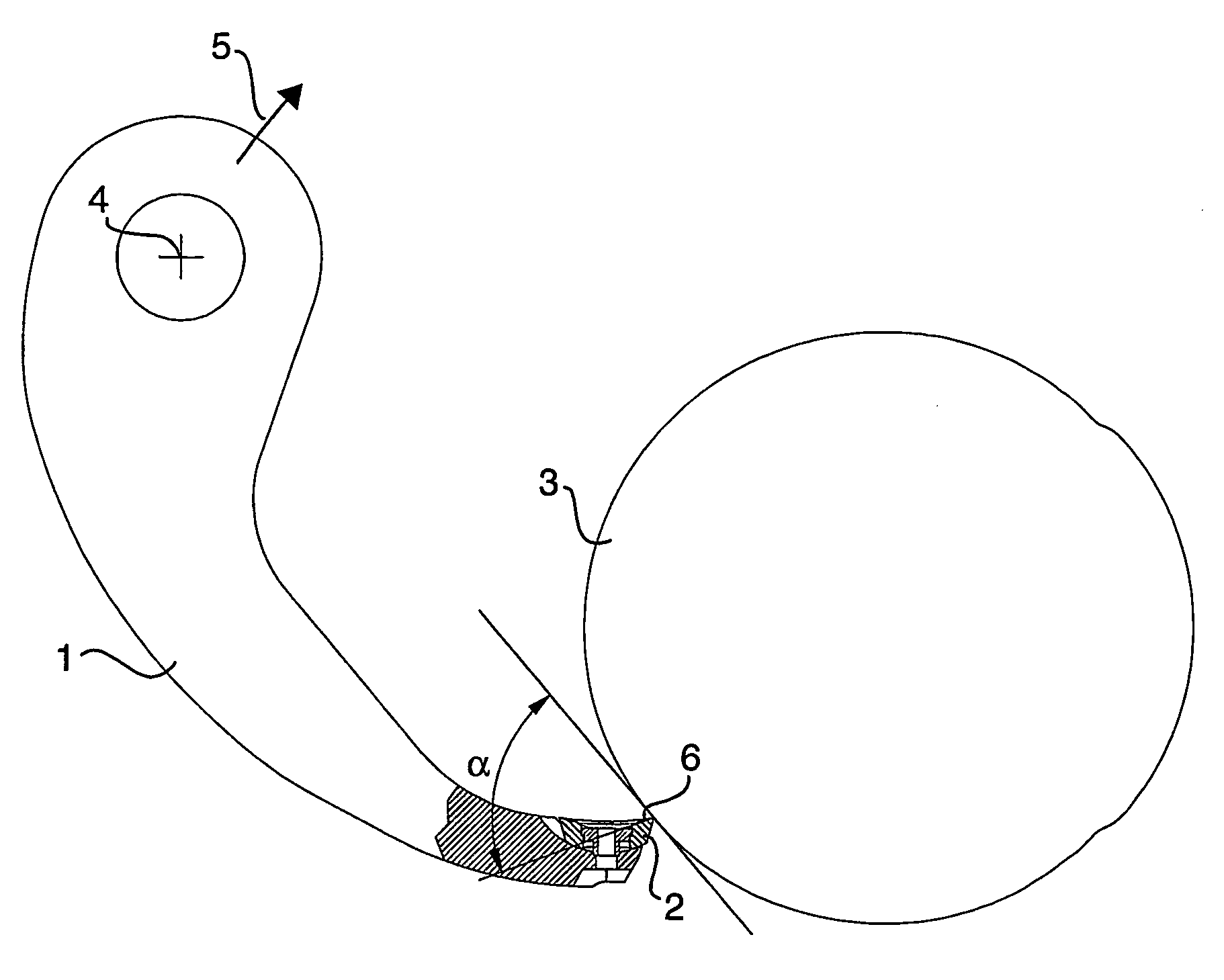
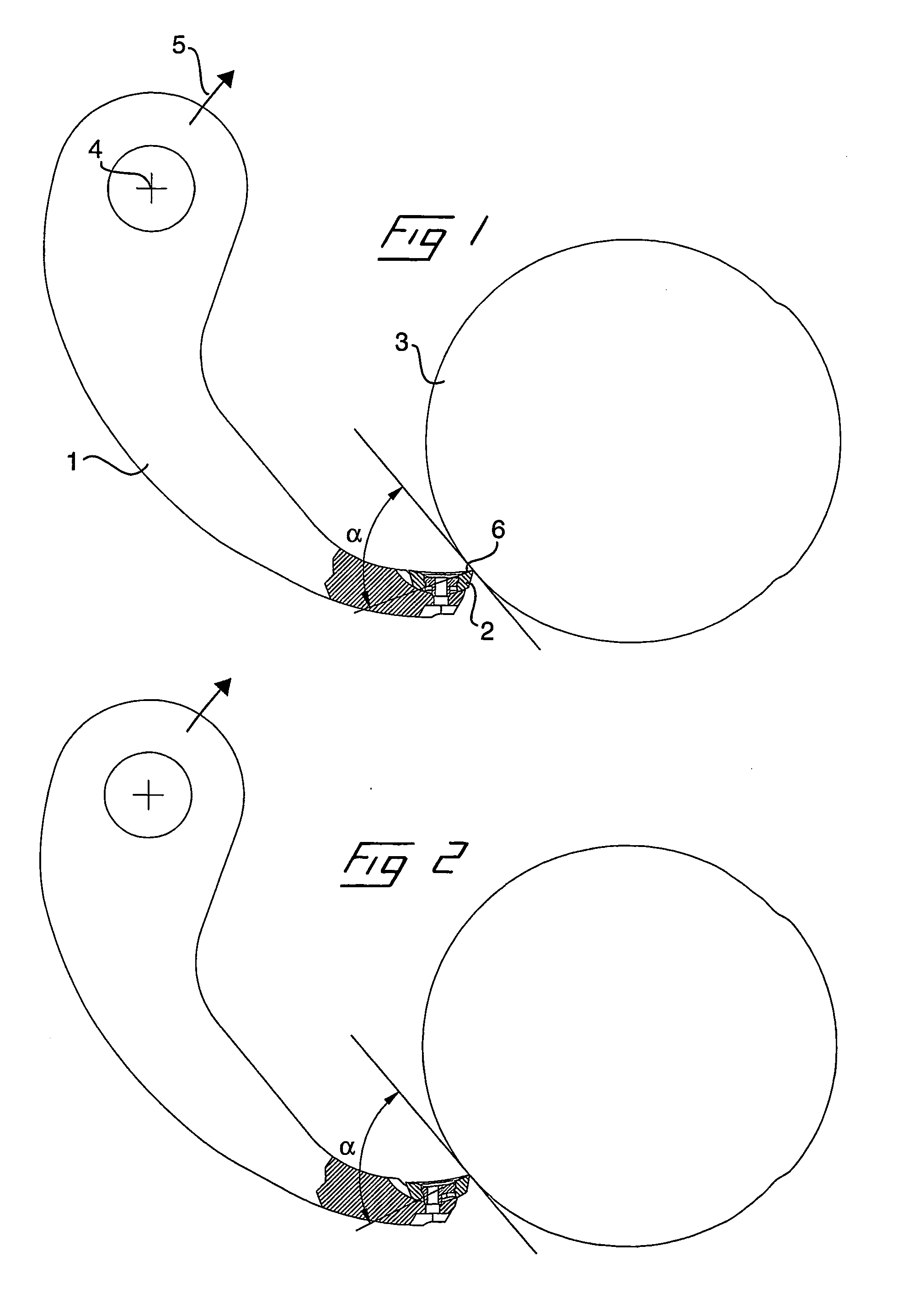
[0048] In the present description, the terms transversely, cross-section etc, relate to a direction transversely to the longitudinal extent of the barking arm, parallel to the direction of feeding of the logs. The terms in the longitudinal direction, longitudinal section etc. relate to a direction in the longitudinal extent of the barking arm, perpendicular to the direction of feeding of the logs. By front end of the barking arm is meant the outer free end of the barking arm including the tool seat for the barking tool, which is adapted to be applied against the circumferential surface of a log which is to barked.

[0049] Reference is first made to FIGS. 1 and 2, which schematically show a barking device comprising a barking arm 1 and a barking tool 2 during barking of a log 3. The barking arm is, by means of a pivot joint, with its centre of turning at the point 4, pivotally connected at its inner end to a rotatable, annular rotor (not shown), which is adapted to rotate in the direc...


PUM


Abstract

The invention relates to a barking device comprising a barking arm (1) and a barking tool (2) which is mountable in a tool seat of the barking arm. The barking tool comprises a convex mounting surface (13), while the seat surface (7) of the barking arm is concave. The barking tool is, with the aid of a connecting means, mountable in the tool seat and displaceable by rotating displacement. The connecting means comprises a screw (18) and a sleeve-like nut (21). The head (20, 23) of one of the connecting means parts (18, 21) is designed to prevent displacement and rotation.

Description

[0001] The present invention relates to the field of barking of logs and, more specifically, to barking machines referred to as rotation ring barkers which comprise an annular rotor on which a plurality of swinging arms are pivotally mounted. Barking tools provided with barking edges are mounted at the free outer ends of the swinging arms. The swinging arms are biased inwards to the centre of the rotor in such a manner that, when the rotor is rotated and a log that is to be barked is simultaneously longitudinally fed through the centre of the rotor, the barking edges of the barking tools will be applied against the circumferential surface of the log so that its bark is shorn off in helical strips. The invention relates to a barking device and a barking tool for such barking machines, which make it possible to set the barking tool at different contact angles to the circumferential surface of the log in order to adjust the contact angle to the circumstances with regard to, for example...

Claims


Application Information

Patent Timeline
Patent Type & Authority Applications(United States)
IPC IPC(8): B27L1/00B23B27/16B27L1/08
CPCB23B27/1655B23B2200/088B23B2200/162B23B2200/163B27L1/08B23B2205/08B23B2205/12B23B2260/106B23B2200/3618
Inventor ERIKSSON, BROR
Owner IGGESUND TOOLS
Why Eureka
Try Eureka