Opitcal projection and image sensing apparatus

a technology of image sensing and optical projection, which is applied in the field of optical projection and image sensing apparatus, can solve the problems of increasing the cost of the image sensing system b>130/b>, the difficulty of saving manufacturing cost, and increasing the complexity of design and manufacture, so as to reduce the manufacturing cost

Inactive Publication Date: 2007-11-15
YOUNG OPTICS
View PDF16 Cites 181 Cited by
  • Summary
  • Abstract
  • Description
  • Claims
  • Application Information

AI Technical Summary

Benefits of technology

[0008]Accordingly, an objective of the present invention is to provide an optica

Problems solved by technology

However, in the conventional optical projection and image sensing apparatus 100, since the optical projection system 120 and the image sensing system 130 are separated, the devices (e.g. lens set) in the optical projection system 120 and the image sensing system 130 can

Method used


Image

  • Opitcal projection and image sensing apparatus
  • Opitcal projection and image sensing apparatus
  • Opitcal projection and image sensing apparatus

Examples


Embodiment Construction

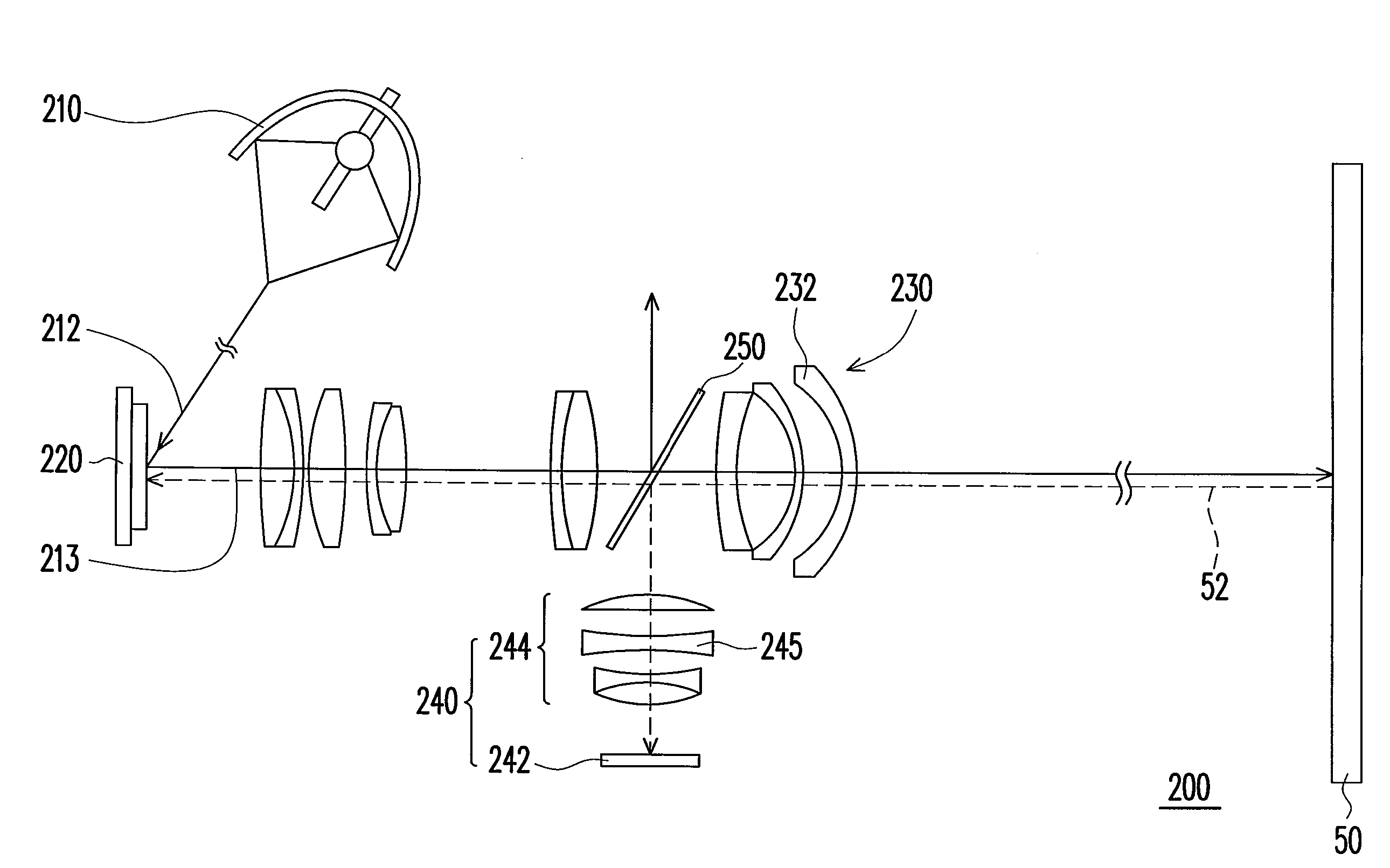
[0020]FIG. 2 is a schematic view of an optical projection and image sensing apparatus according to an embodiment of the present invention. Referring to FIG. 2, the optical projection and image sensing apparatus 200 of the present embodiment comprises a light source 210, a light valve 220, a first lens set 230, a sensing module 240, and a beam splitter 250. The light source 210 is used to provide an illumination light 212. The light valve 220 is disposed on the optical path of the illumination light 212, so as to convert the illumination light 212 to an image light 213. The first lens set 230 is disposed on the optical path of the image light 213 for projecting the image light 213 to display an image on a screen 50. The sensing module 240 is used to sense a sensing light from the image on the screen 50. The beam splitter 250 is disposed on the optical path of the image light 213 and the optical path of the sensing light 52. The beam splitter 250 is used to reflect a part of the sensi...


PUM


Abstract

An optical projection and image sensing apparatus including a light source, a light valve, a first lens set, a sensing module, and a beam splitter is provided. The light valve is used to convert an illumination light from the light source to an image light beam. The first lens set is used to project the image light to display an image on a screen, and the sensing module is used to sense a sensing light from the image on the screen. The beam splitter is disposed on the optical paths of the image light and the sensing light from the image on the screen. One of the sensing module and the light valve is disposed on the optical path of the sensing light passing through the beam splitter, and the other is disposed on optical path of the sensing light reflected by the beam splitter.

Description

CROSS-REFERENCE TO RELATED APPLICATION[0001]This application claims the priority benefit of Taiwan application serial no. 95116328, filed May 9, 2006. All disclosure of the Taiwan application is incorporated herein by reference.BACKGROUND OF THE INVENTION[0002]1. Field of Invention[0003]The present invention relates to an image display apparatus. More particularly, the present invention relates to an optical projection and image sensing apparatus.[0004]2. Description of Related Art[0005]FIG. 1A is a schematic perspective view of a conventional optical projection and image sensing apparatus, and FIG. 1 B is a side view of the optical projection and image sensing apparatus of FIG. 1 A. Referring to FIG. 1 A and FIG. 1 B, the conventional optical projection and image sensing apparatus 100 comprises a circuit board 110, an optical projection system 120, an image sensing system 130, and a screen 140. The optical projection system 120 and the image sensing system 130 are coupled to a circ...

Claims


Application Information

Patent Timeline
IPC IPC(8): G03B21/26
CPCG03B21/26H04N9/3197H04N9/3102G06F3/0425G06F3/0304H04N9/3179H04N9/3194G06F3/0421H04N9/317
Inventor SHYU, JYH-HORNGCHENG, CHU-MING
Owner YOUNG OPTICS
Why Eureka
Try Eureka