
Interferometer using vertical-cavity surface-emitting lasers

Inactive Publication Date: 2007-11-15
KYUNGPOOK NAT UNIV IND ACADEMIC COOP FOUND
View PDF12 Cites 14 Cited by
  • Summary
  • Abstract
  • Description
  • Claims
  • Application Information

AI Technical Summary

Benefits of technology

[0008]The present invention has been made to solve the foregoing problems of the prior art and therefore an aspect of the invention is to provide an interferometer which incorporates a single mode VCSEL to facilitate miniaturization, save manufacturing cost, and further shorten optical path through integration of parts thereby improving precision.
[0009]Another aspect of the invention is to provide an interferometer which is realized through single optical alignment of parts and has a larger value of alignment tolerance over existing interferometers, thereby to save manufacturing cost over the existing interferometers while enabling miniature size.

Problems solved by technology

However, existing interferometers adopt a gas laser, which increases the volume of an optical system.
This makes it difficult to miniaturize the location sensor using an interferometer.
However, this type of laser is difficult and expensive to fabricate and thus can be rarely mass-produced.

Method used


Image

  • Interferometer using vertical-cavity surface-emitting lasers
  • Interferometer using vertical-cavity surface-emitting lasers
  • Interferometer using vertical-cavity surface-emitting lasers

Examples


Embodiment Construction

[0022]The present invention will now be described more fully hereinafter with reference to the accompanying drawings, in which preferred embodiments of the invention are shown.

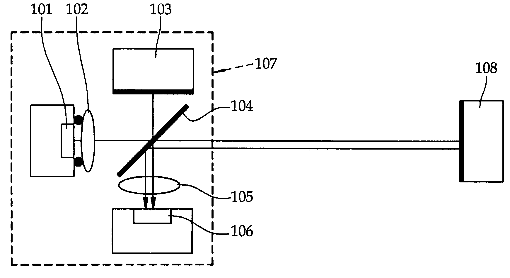
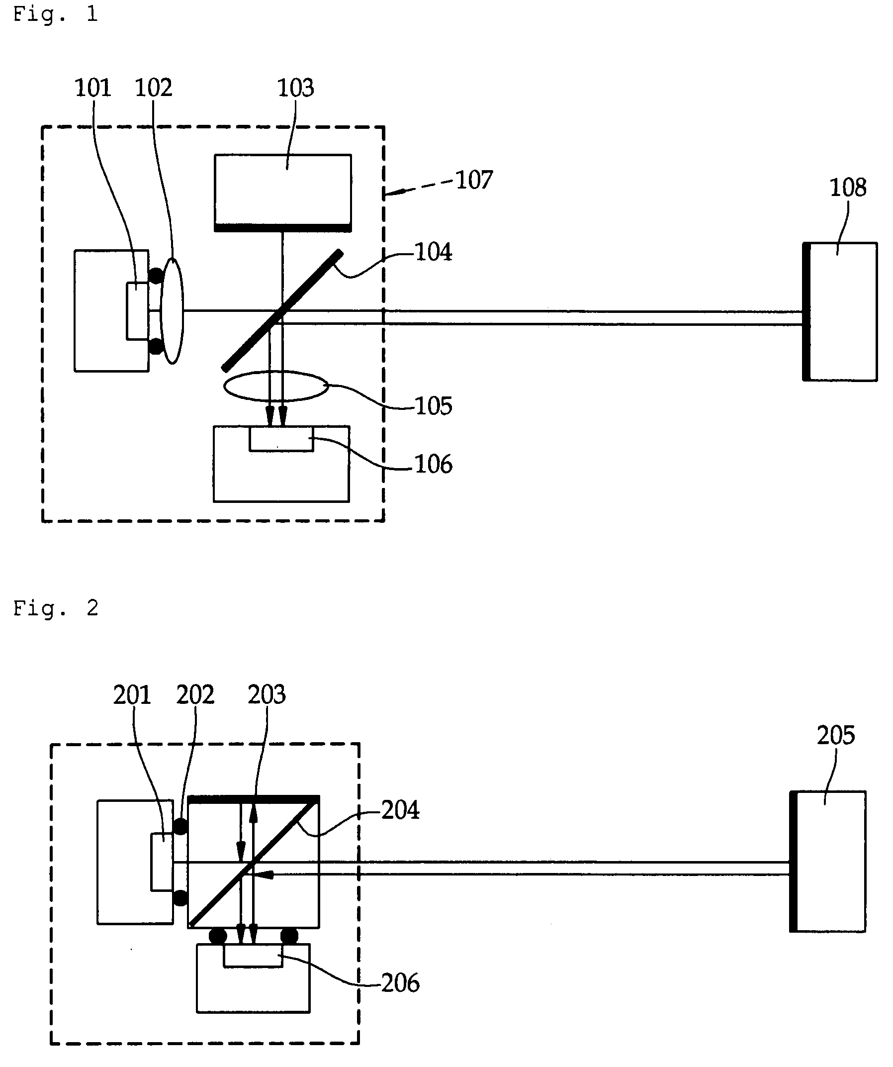
[0023]This disclosure provides an example of a miniature interferometer realized by using a single mode VCSEL as a light source while utilizing a variety of merits of the VCSEL. FIG. 1 is a conceptual view illustrating an interferometer according to a first embodiment of the invention, in which a Michelson interferometer is realized by using a single mode VCSEL 101.

[0024]Light from the VCSEL 101 is converted into a collimated beam through a lens 102 and then reaches a beam splitter 104. According to the type of the beam splitter 104, the beam is divided into two portions at a specific ratio. The beam splitter 104 reflects the first beam portion toward a first mirror 103 while transmitting the second beam portion toward a second mirror 108. The first beam portion is reflected from the first mirror 103 toward th...


PUM


Abstract

An interferometer which incorporates a single mode VCSEL to facilitate miniaturization through integration of parts. The interferometer includes a beam splitter for partially reflecting and transmitting light; a single mode vertical-cavity surface-emitting laser for generating a beam of light perpendicular to a wafer; a first mirror fixedly perpendicular to the first path to reflect the portion of light reflected from the beam splitter; a second mirror movably arranged along the second path to reflect the beam portion transmitted through the beam splitter. A photodetector arranged along the second path detects the beam portion reflected from the first mirror and transmitted again through the beam splitter and the beam portion reflected from the second mirror and reflected again from the beam splitter to locate the second mirror based on an interference fringe created by a difference in the paths between the two beam portions.

Description

CROSS REFERENCE TO RELATED APPLICATION[0001]This application claims the benefit of Korean Patent Application No. 2006-0043198 filed on May 15, 2006, in the Korean Intellectual Property Office, the disclosure of which is incorporated herein by reference.BACKGROUND OF THE INVENTION[0002]1. Field of the Invention[0003]The present invention relates to an interferometer using a vertical-cavity surface-emitting laser (VCSEL), and more particularly, to an interferometer which incorporates a single mode VCSEL to facilitate miniaturization through integration of parts, save manufacturing cost, and improve precision.[0004]2. Description of the Related Art[0005]An interferometer is an optical device utilizing superposition of wave which has a long history. Before the invention of the laser, pseudo-monochromatic light had been produced by transmitting light from a mercury lamp or natural light through a filter in order to create an interference fringe. After the introduction of the laser, the i...

Claims


Application Information

Patent Timeline
IPC IPC(8): G01C3/08
CPCG01B2290/30G01B9/02H01S5/423
Inventor JU, YOUNG-GU
Owner KYUNGPOOK NAT UNIV IND ACADEMIC COOP FOUND
Learn More