Bi-Stable Electrowetting Optical Element and Driving Method Therefor

a technology of optical elements and electrowetting, applied in the field of optical elements, can solve the problems of power consumption, albeit lower, still quite high, power consumption, etc., and achieve the effect of improving power consumption characteristics

Inactive Publication Date: 2007-11-15
KONINKLIJKE PHILIPS ELECTRONICS NV
View PDF3 Cites 25 Cited by
  • Summary
  • Abstract
  • Description
  • Claims
  • Application Information

AI Technical Summary

Benefits of technology

[0003] It is therefore an object of the present invention to provide an optical el

Problems solved by technology

One problem, however, with optical elements of the above mentioned kind is that the power consumption, albeit lower than for optical

Method used


Image

  • Bi-Stable Electrowetting Optical Element and Driving Method Therefor
  • Bi-Stable Electrowetting Optical Element and Driving Method Therefor
  • Bi-Stable Electrowetting Optical Element and Driving Method Therefor

Examples


first embodiment

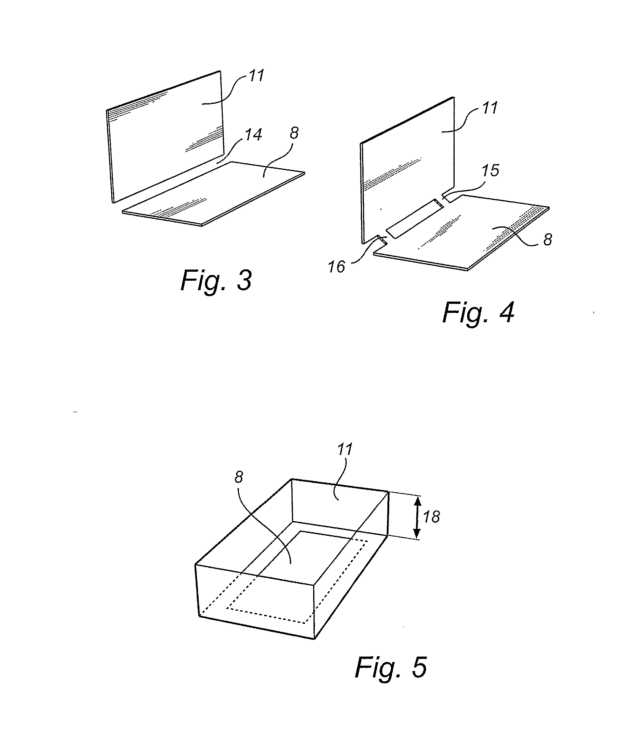
[0033]FIG. 3 illustrates hydrophobic insulating layers, arranged in accordance with the invention. The first electrode 7 and the first hydrophobic layer 8 are planar and located in the back wall of the cell as seen from a user, watching a display. The second electrode 10 and the second hydrophobic layer 11 then extend substantially perpendicular to plane of the first electrode, and are then arranged at a side wall (3 in FIG. 2a).

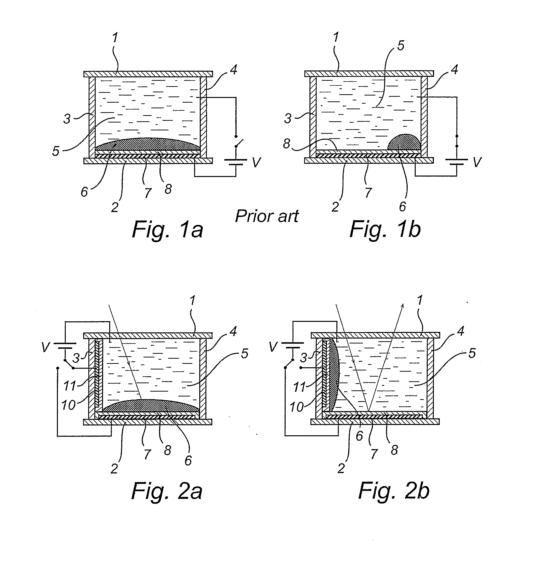
[0034] It should be understood that the first and second electrodes 7, 10 could also be parallel, but the perpendicular arrangement provides the additional advantage of keeping the oil 6 substantially out of the optical path of incoming and reflected light, since the white back wall 2 can be completely uncovered.

[0035] As illustrated in FIG. 3 a continuous gap 14 may be provided between the first hydrophobic layer 8 and the second hydrophobic layer 11. This prevents any transport of the oil 6 between the first and second hydrophobic layers 8, 11, when no vo...

second embodiment

[0036]FIG. 4 illustrates hydrophobic insulating layers, arranged in accordance with the invention. In this embodiment one or more hydrophobic material bridges 15, 16 are provided, which interrupt the otherwise continuous gap between the first hydrophobic layer 8 and the second hydrophobic layer 11. While such bridges 15, 16 to some extent create a risk of unintentional transport of oil 6 between the first and second hydrophobic layers 8, 11, they also make the switching between the two states more reliable by guiding the oil 6 between the first and second hydrophobic layers 8, 11. This reduces the risk that some or all of the oil 6 unintentionally remains on a hydrophobic layer similar to the situation in FIG. 1b.

[0037] The width of the bridges 15, 16 should be chosen experimentally to be wide enough to provide the guiding function, but small enough to avoid unintended transport of oil 6 in a relaxed state.

third embodiment

[0038]FIG. 5 illustrates hydrophobic insulating layers, arranged in accordance with the invention. As illustrated, it is preferred to let the second electrode extend adjacent to more than one side wall of the cell, and even more preferred adjacent to all side walls of the cell. This allows a decreased thickness 18 of the cell even though the total area of the second electrode 10 and the second hydrophobic layer 11 can be retained. The advantage of this is not only a thinner display, when the optical element is used in a display. More important, the viewing angle of the display is improved.

[0039] As described above, the optical element is used as a pixels in a display device, comprising a plurality of such optical elements. However, the optical element may also be used in other applications, such as a switchable diaphragm, a shutter or a colour filter.

[0040] In summary, the invention relates to an optical element, used e.g. in an electrowetting display device comprising a number of ...


PUM


Abstract

The present invention relates to an optical element, used e.g. in an electrowetting display device comprising a number of pixels, arranged in an array. Each optical element comprises a cell filled with a polar conductive fluid (5), such as a water solution, and a non-polar fluid (6), such as an oil. The cell further comprises first and second planar electrodes (7, 10), covered with first and second hydrophobic layers (8, 11). By applying a voltage between on one hand the first fluid and on the second hand alternately the first or second electrodes (7, 10), the oil (6) is forced to migrate between the first and second hydrophobic layers (8, 11). Thus a bi-stable, energy efficient optical element is provided.

Description

FIELD OF THE INVENTION [0001] The present invention relates to an optical element, comprising a closed cell, containing a first fluid and a second fluid, wherein the first fluid is conductive and the second fluid is coloured and immiscible with the first fluid, a first electrode, covered with a first hydrophobic, insulating layer and located at a first wall in the cell, the voltage between the first electrode and the first fluid being controllable in order to control the area of the first hydrophobic layer that contacts the first fluid, and thereby the amount of light that is transmitted through the cell in a direction perpendicular to the first wall. BACKGROUND OF THE INVENTION [0002] Such an optical element, forming part of a display device, known as an electrowetting display, is disclosed for example in WO, 03 / 071347, A1. The electrowetting functionality provides a display with excellent brightness and contrast, and a relatively low power consumption compared to many other displa...

Claims


Application Information

Patent Timeline
IPC IPC(8): G02B26/02G09F9/37
CPCG09F9/372G02B26/005G09F9/37G02B26/00
Inventor HAYES, ROBERT ANDREWMASSARD, ROMARIC MATHIEUFEENSTRA, BOKKE JOHANNES
Owner KONINKLIJKE PHILIPS ELECTRONICS NV
Why Eureka
Try Eureka