Disk drive

a technology of disk drive and high-pass filter, which is applied in the field of disk drive, can solve the problems of increasing the cutoff frequency of high-pass filter to several megahertz, degradation of error rate, and degradation of error rate, and achieve the effect of minimizing the error recovery tim

Inactive Publication Date: 2007-11-15
WESTERN DIGITAL TECH INC
View PDF16 Cites 7 Cited by
  • Summary
  • Abstract
  • Description
  • Claims
  • Application Information

AI Technical Summary

Benefits of technology

[0014] Embodiments in accordance with the present invention provide a magnetic disk drive capable of achieving error recovery stably in a simple configuration in the event of thermal asperity (TA) and minimizing the error recovery time required, and a method for controlling the disk drive. According to the specific embodiment of the present invention shown in FIG. 2, if TA occurs, a cutoff frequency of a high-pass filter to which a data read signal is input is first increased and a loop gain of a low-order FIR filter 215 connected in series to an FIR filter 214 is also increased as high as possible. Next, a Viterbi decoder 216 to which a signal is input from the low-order FIR filter 215 provides feedback to the low-order FIR filter 215 so that an input signal error becomes a minimum. Tap coefficients of the low-order FIR filter 215 are thus optimized.

Problems solved by technology

Accordingly, if the thermal asperity occurs, an error recovery process has been traditionally performed, which increases the cutoff frequency of the high-pass filter to several megahertz.
This causes the degradation in error rate.
For this reason, the use of the perpendicular recording scheme results in the contradiction that the process for error recovery causes the degradation in error rate.
If TA occurs, therefore, an error recovery effect cannot be obtained just by increasing the cutoff frequency of the high-pass filter.
In the meantime, calibration becomes a time-consuming task since a large number of data sectors must be read to optimize the tap coefficients stably.
In other words, optimizing all taps requires slow feedback and is likely to result in system divergence if feedback is accelerated.
This requires a large amount of memory capacity.

Method used


Image

  • Disk drive
  • Disk drive
  • Disk drive

Examples


Embodiment Construction

[0020] Embodiments in accordance with the present invention relate to a disk drive, and more particularly, to adjusting a filtering coefficient of a signal which has been read out from a disk drive.

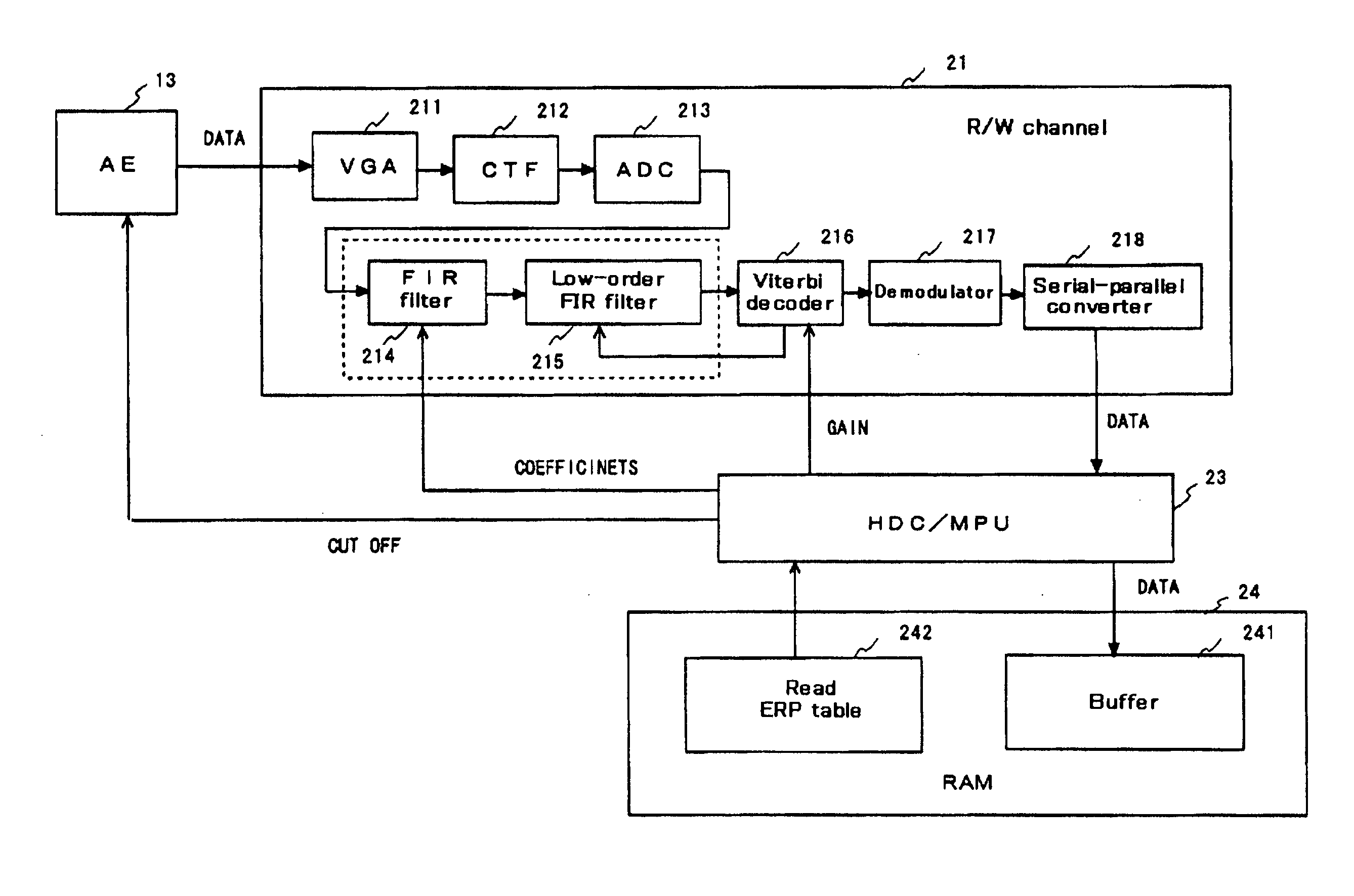
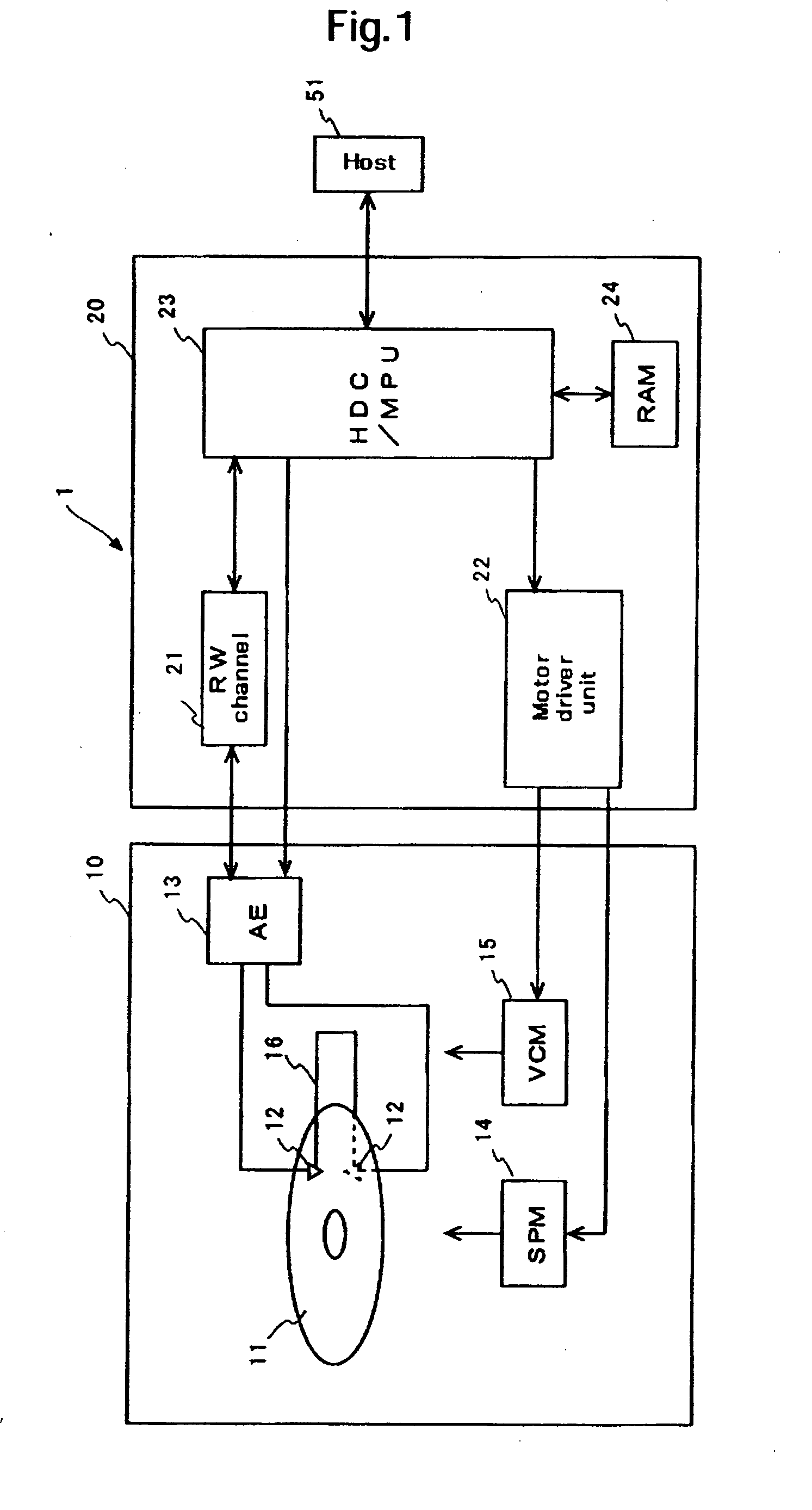
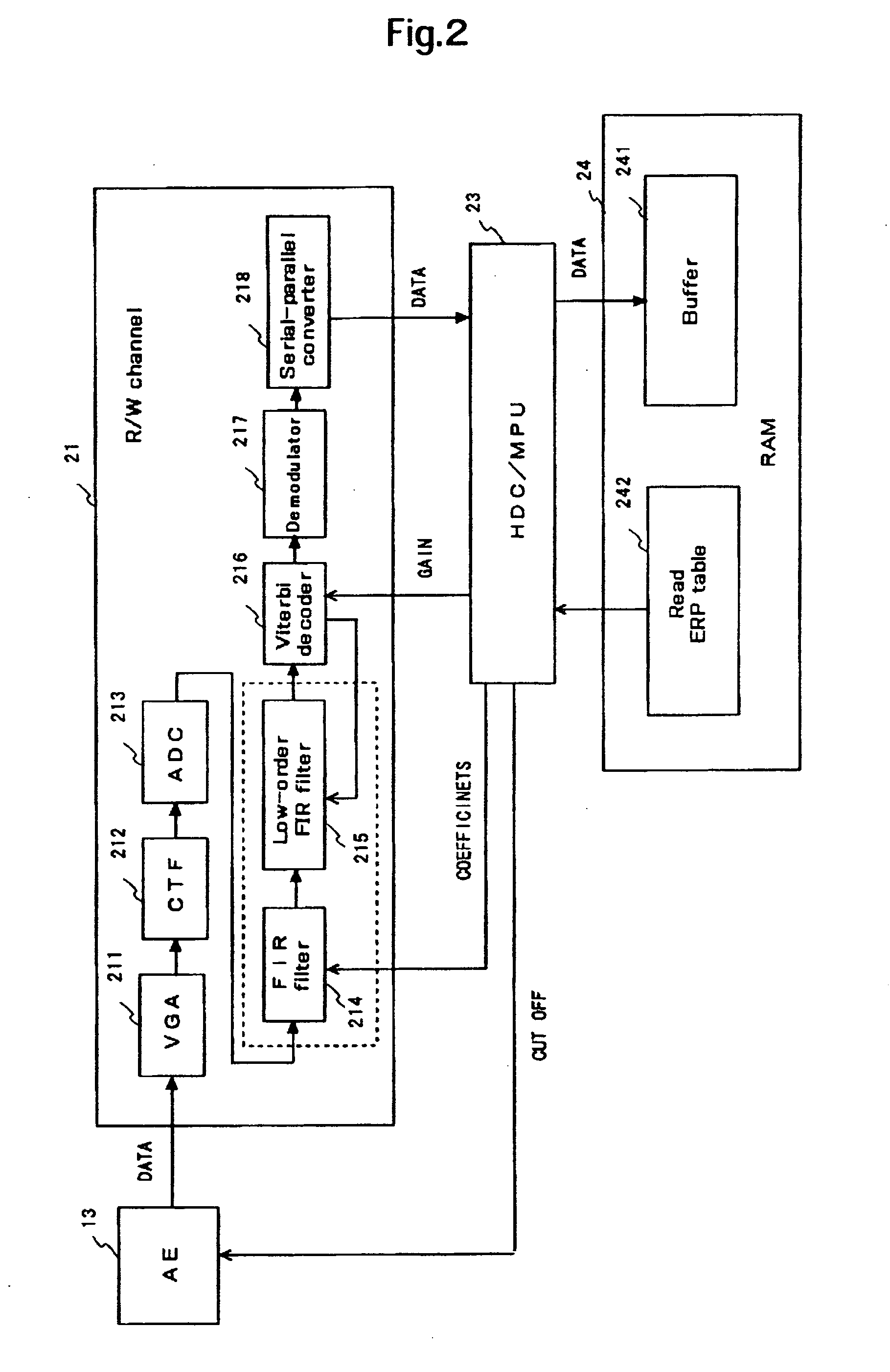
[0021] A disk drive according to an embodiment of the present invention includes a head that reads out data from a disk; a low cut filter that selectively uses a first cutoff frequency and a second cutoff frequency to cut off part of a signal transmitted from the head; a waveform control filter that has a plurality of filtering coefficients and controls a waveform of a signal transmitted from the low cut filter; and a filtering coefficient controller that controls the filtering coefficients of the waveform control filter in accordance with a signal from the waveform control filter. When the low cut filter uses the first cutoff frequency, the filtering coefficient controller controls part of the plural filtering coefficients at a first feedback gain level. When the low cut filter uses the...


PUM

PropertyMeasurementUnit
cutoff frequencyaaaaaaaaaa
flexibleaaaaaaaaaa
recording densityaaaaaaaaaa

Abstract

Embodiments in accordance with the present invention provide a magnetic disk drive capable of achieving error recovery stably in a simple configuration in the event of thermal asperity (TA) and minimizing the error recovery time required, and a method for controlling the disk drive. According to one embodiment, if TA occurs, a cutoff frequency of a high-pass filter to which a data read signal is input is first increased and a loop gain of a low-order finite impulse response (FIR) filter connected in series to an FIR filter is also increased as high as possible. Next, a Viterbi decoder to which a signal is input from the low-order FIR filter provides feedback to the low-order FIR filter so that an input signal error becomes a minimum. Tap coefficients of the low-order FIR filter are thus optimized.

Description

CROSS-REFERENCE TO RELATED APPLICATION [0001] The instant nonprovisional patent application claims priority to Japanese Patent Application No. 2006-120868, filed Apr. 25, 2006 and incorporated by reference in its entirety herein for all purposes. BACKGROUND OF THE INVENTION [0002] Devices using various types of media such as optical disks, magnetic optical disks, and a flexible magnetic disk, are known in the art as disk drives. Among them, hard disk drives (hereinafter referred to as HDDs) have become popular as storage devices for computers to such an extent that they are one of the storage devices indispensable for modern computer systems. Further, not limited to the computers as described above, HDDs are expanding more and more in application due to their excellent properties. For example, HDDs are used for moving picture recording / reproducing devices, car navigation systems, cellular phones, and removable memories for use in digital cameras. [0003] The magnetic disks used in th...

Claims


Application Information

Patent Timeline
Patent Type & Authority Applications(United States)
IPC IPC(8): G11B20/10
CPCG11B20/10009G11B20/10027G11B20/10046G11B20/10481G11B2220/2516G11B20/1833G11B27/36G11B2005/0016G11B2020/1863G11B20/18
Inventor IKEDA, MASAOMIMATSUI, TAKAOKOIZUMI, MASAHIKOTANIGUCHI, MASATONAKAO, KOHJIMAEDA, HIDEAKI
Owner WESTERN DIGITAL TECH INC
Why Eureka
Try Eureka