Microfluidic analytical apparatus

Active Publication Date: 2007-11-15
MONOGRAM BIOSCIENCES
View PDF16 Cites 0 Cited by
  • Summary
  • Abstract
  • Description
  • Claims
  • Application Information

AI Technical Summary

Benefits of technology

[0012] Apparatus according to the invention assist in providing multiple microfluidic manipulations at high throughput rates to allow for continuous processing of high number of analyses at high rates of speed. The complexity of mass screening programs is reduced for example by the sim

Problems solved by technology

One drawback however is that these methods all require heating and cooling of the chip substrate.
Given variations between substrates in glass transition temperatures and varying exposure to both ambient and elevated temperatures, the resulting chips often include some level of warpage and/or minor defects.
These irregularities can interfere with the in

Method used


Image

  • Microfluidic analytical apparatus
  • Microfluidic analytical apparatus
  • Microfluidic analytical apparatus

Examples


Example

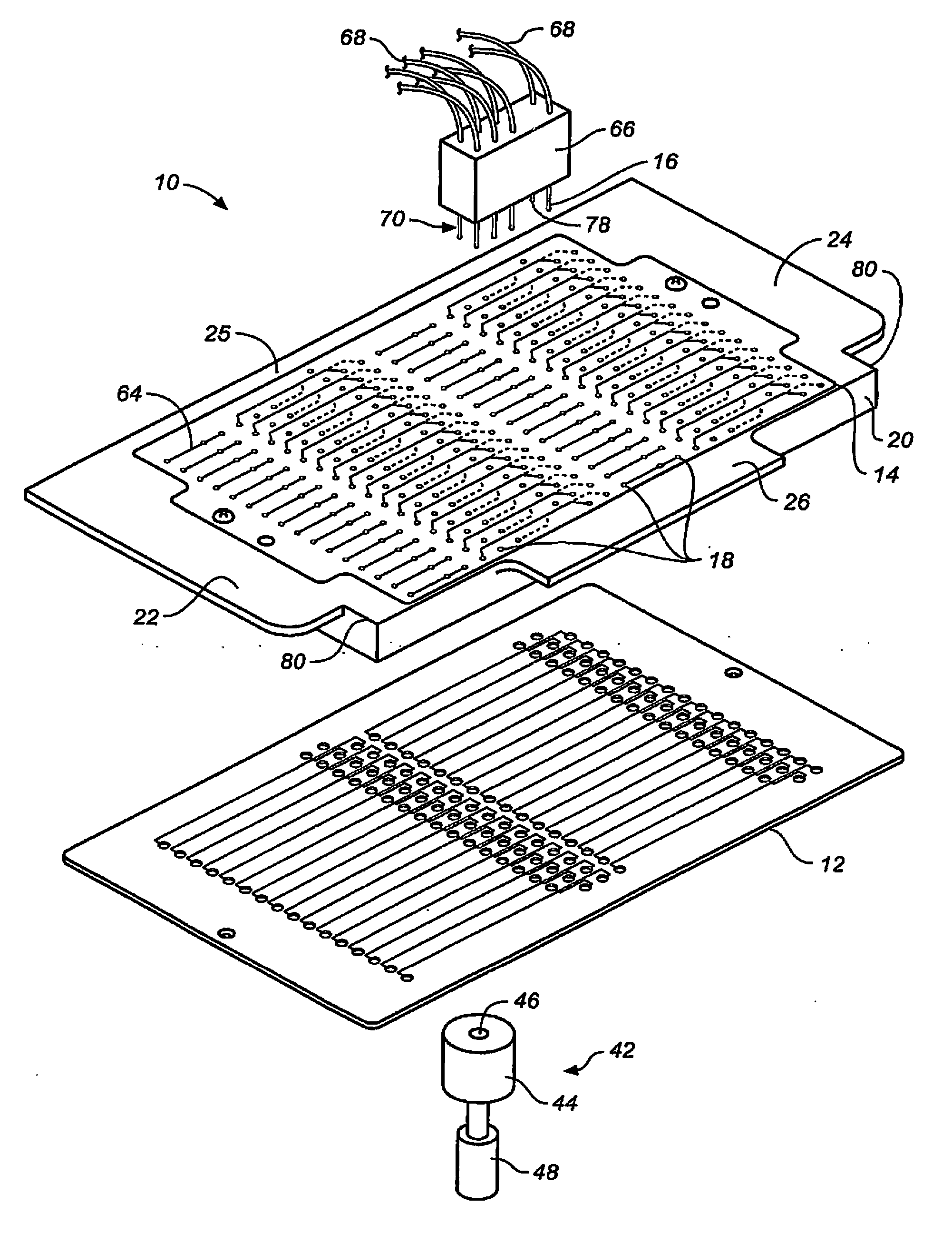
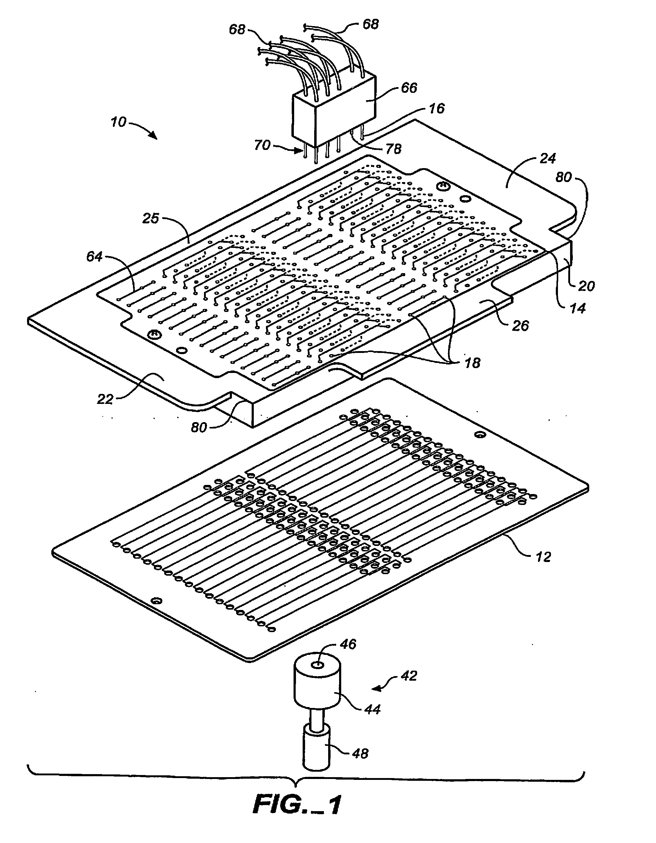
[0019] With reference to FIGS. 1 and 2, there is seen an embodiment 10 of the present invention featuring a microfluidic card 12 paired with a circuit card 14 and conductive fingers 16 paired with conductive pads 18 of the circuit card 14. The conductive fingers 16 are electrically connected to and in electrical communication with a power source (not shown) and provide voltages to the circuit card 14 during analysis of sample within the microfluidic card 12. A detection system is employed for analysis of sample materials. In this embodiment of the invention, a microscope 42 is used as a part of the detection system; however, various detection systems known in the art may be used.

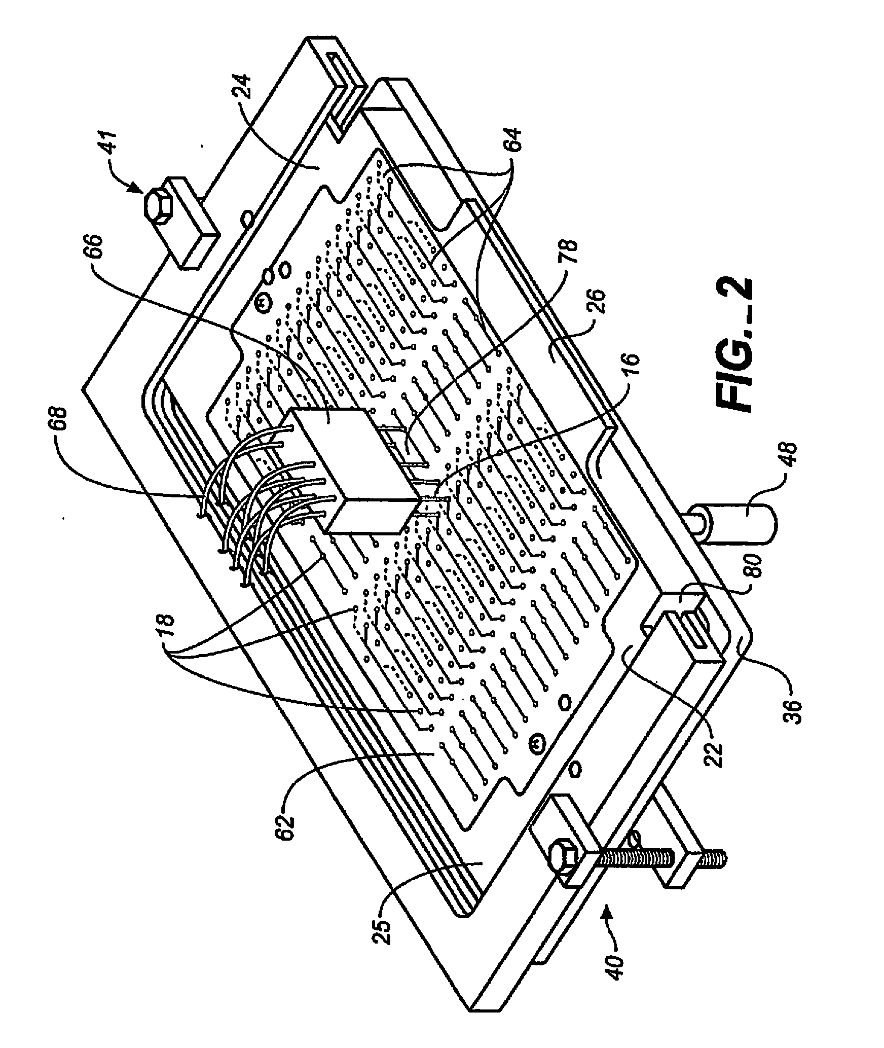
[0020] A holder 20 having wings 22, 24 and 26 holds the circuit card 14. Wing 26 can be used to grip the holder 20. The holder 20 is made from a rigid material such as for example, a rigid plastic.

[0021] With reference to FIGS. 2 and 3 it is seen that wings 22 and 24 of circuit card 14 slide within partial...


PUM

PropertyMeasurementUnit
Electrical conductoraaaaaaaaaa
Electric potential / voltageaaaaaaaaaa

Abstract

A microfluidic analytical apparatus (10) comprising a microfluidic card pairing (12) with a corresponding circuit card (14) and the circuit card pairing (12) with corresponding conductive fingers (16). The microfluidic card (12) has a plurality of channels (32) and ports (54) on a top surface of the card in a desired configuration, the ports (54) in fluid communication with the channels (32). The circuit card (14) has a plurality of conductive pins (60) projecting from a bottom surface of the card and having a configuration that corresponds to the particular configuration of the ports (54) of the microfluidic card (12) that is paired with. The circuit card (14) is received within a holder (20) that provides that provides multiple functions. Conductive pads (18) are disposed on a top surface of the circuit card (14), the pads (18) in electrical communication with the conductive pins (60) and corresponding to a configuration of conductive fingers (16) connected to a power source to provide voltage to the microfluidic card (12) for analytical operations. Additionally, detection difficulties associates with non-uniformities present on the card surface are overcome using a detection system incorporating a compliantly mounted microscopic head.

Description

[0001] This invention relates in general to microfluidic devices and analytical apparatus for using microfluidic devices to conduct chemical and biochemical sample analysis. BACKGROUND OF THE INVENTION [0002] Today's microfluidic chips are capable of reliably carrying out many chemical and reactions and analytical assays using minimal amounts reagents. These high throughput cards incorporate arrays of fluidic networks, each network having a multitude of ports or reservoirs and microchannels associated therewith. Examples of microfluidic chips, fluidic arrays, and their methods use are described in U.S. Pat. Nos. 5,750,015; 6,103,199 and published patent application Ser. No. 99 / 19717 assigned to the assignee and hereby incorporated by reference. In each network, reservoirs are provided for introduction of sample, reagents, test compounds, or liquid media. In some cases, microfluidic devices are manufactured with media already in the channels or reservoirs as appropriate. [0003] Micro...

Claims


Application Information

Patent Timeline
IPC IPC(8): B01L11/00B01L99/00B01L9/00C02F11/00C25B13/00G01N27/447H01S3/00H05K3/22
CPCB01J2219/00783B01J2219/00804H01L2924/0002B01J2219/0081B01J2219/0095B01L9/527B01L2200/02B01L2200/025B01L2300/0816B01L2400/0415G01N27/44704G01N27/44782G01N27/44791H05K3/222H01L2924/00
Inventor BJORNSON, TORLEIFMAHER, KEVIN
Owner MONOGRAM BIOSCIENCES
Why Eureka
Try Eureka