System for electrical contacting

Inactive Publication Date: 2007-11-15
ROBERT BOSCH GMBH
View PDF7 Cites 0 Cited by
  • Summary
  • Abstract
  • Description
  • Claims
  • Application Information

AI Technical Summary

Benefits of technology

[0007] In contrast to the related art, the system according to the present invention for the electrical contacting of at least one connection element of an electronic circuit in a hermetically sealed housing with a conductor element has a press-in connection b

Problems solved by technology

In the case of various applications, transmission technology for example, certain boundary conditions do not allow soldering as a method for contacting the connector pins with the electrical conductor el

Method used


Image

  • System for electrical contacting
  • System for electrical contacting
  • System for electrical contacting

Examples


Embodiment Construction

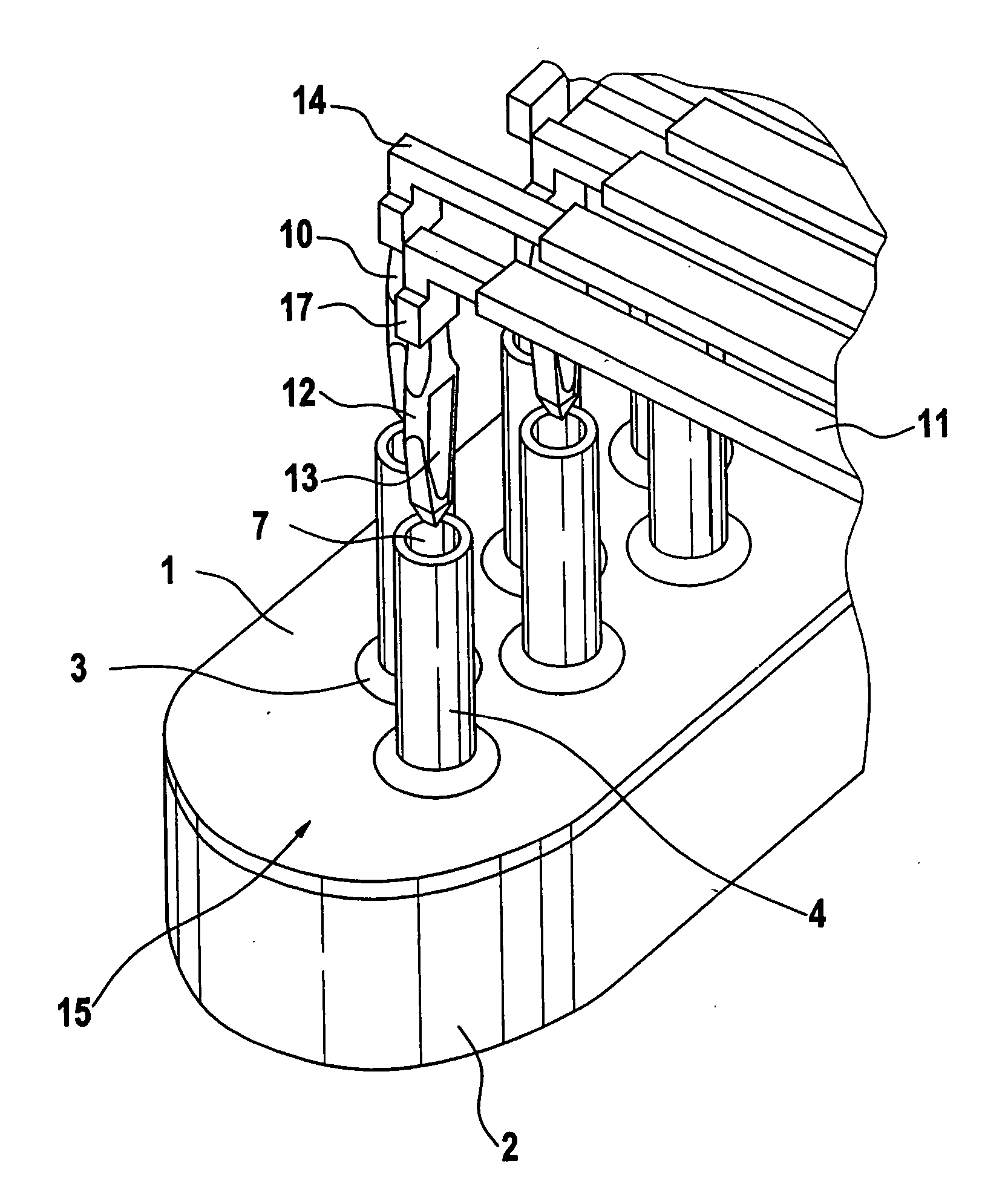
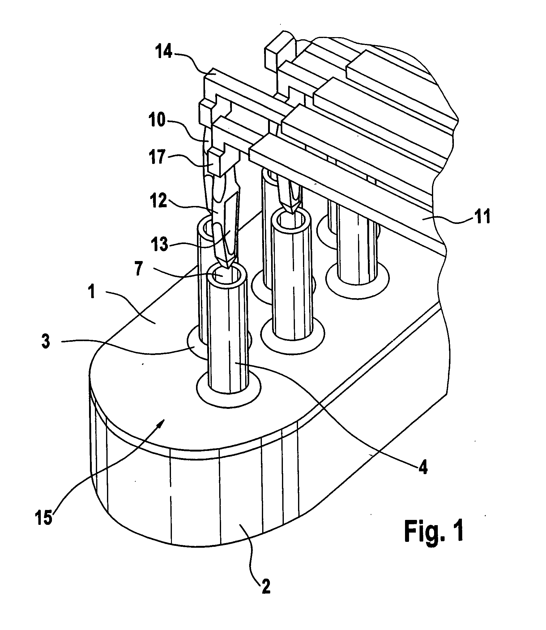
[0019]FIG. 1 illustrates an exemplary embodiment of a system according to the present invention for contacting connection elements 4 with conductor elements 11 prior to a contacting process.

[0020] A hermetically sealed housing 2 in which, for example, an electronic circuit (not illustrated) is situated is shown only schematically. Housing 2 is sealed by a base plate 1. Base plate 1 has openings into which connection elements 4 are inserted. Inside housing 2, connection elements 4 are electrically connected to the electronic circuit. The connection elements are positioned in such a way that they form a connection series 15 having offset connection elements 4. Of course, other systems are possible.

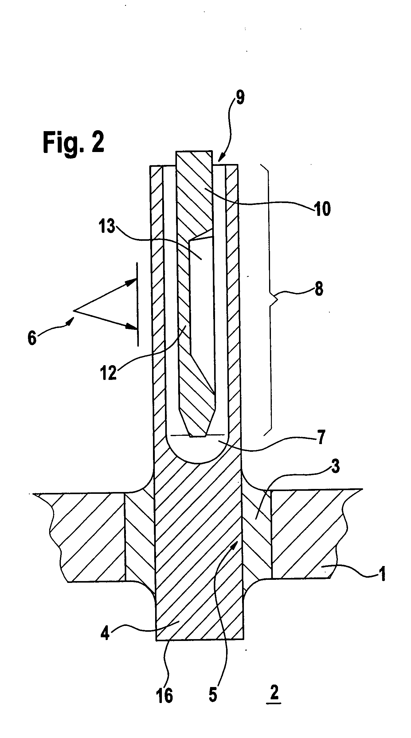
[0021] Connection elements 4 are inserted into base plate 1 in a tight, insulated, secure manner by use of fastening elements 3. This fastening element 3 is preferably made of glass. In each case, glass in the form of a blank is inserted together with a connection element 4 into the openin...


PUM


Abstract

In a system for the electrical contacting of at least one connection element of an electronic circuit in a hermetically sealed housing with a conductor element having a base plate for holding the at least one connection element, the conductor element is provided with a press-in pin which may be pressed-in in one section of the connection element to form a contact.

Description

BACKGROUND OF THE INVENTION [0001] 1. Field of the Invention [0002] The present invention relates to a system for the electrical contacting of at least one connection element of an electronic circuit in a housing with a conductor element. [0003] 2. Description of Related Art [0004] Hermetically sealed housings are currently available in various designs having a variety of electronic circuits, such as sensors or control devices in the field of transmission technology. One design of such a hermetic housing has a base plate through which connector pins for the electrical connector for the circuit inside the housing are inserted. During manufacture the connector pins are inserted into receiving holes in the base plate, which has a glass blank. Melting of the glass at appropriate temperatures and subsequent cooling results in a secure, electrically insulated bond between the connector pins and the base plate. The electronic circuit is electrically connected to the connector pins by use o...

Claims


Application Information

Patent Timeline
IPC IPC(8): H01R13/05H01R12/58
CPCH01R13/05H01R12/58
Inventor MUELLER, HANS-PETERJACOB, WOLFGANGTRESCHER, ULRICH
Owner ROBERT BOSCH GMBH
Why Eureka
Try Eureka