Porous fired granulated body and method for manufacturing the same

Pending Publication Date: 2020-06-11
ITOCHU CERATECH
View PDF4 Cites 0 Cited by
  • Summary
  • Abstract
  • Description
  • Claims
  • Application Information

AI Technical Summary

Benefits of technology

[0035]With the manufacturing method described above, the granulated body after wet granulation is not required to be rehydrated by loading into an autoclave, etc., and reductions in production man-hours and thermal energy cost can be achieved. Also, by spraying the respectiv

Problems solved by technology

However, with the method for manufacturing the porous fired granulated body or the precursor thereof, the granulated body, prepared by tumbling g

Method used


Image

  • Porous fired granulated body and method for manufacturing the same
  • Porous fired granulated body and method for manufacturing the same
  • Porous fired granulated body and method for manufacturing the same

Examples


Example

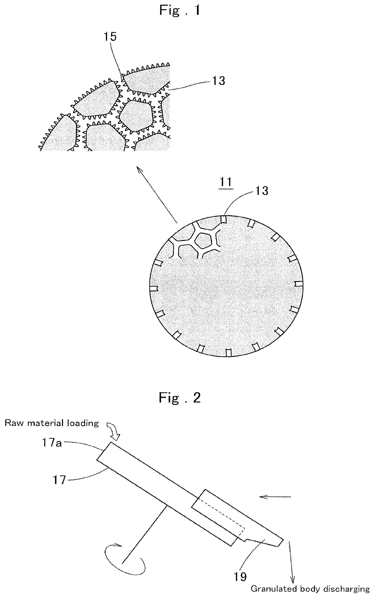
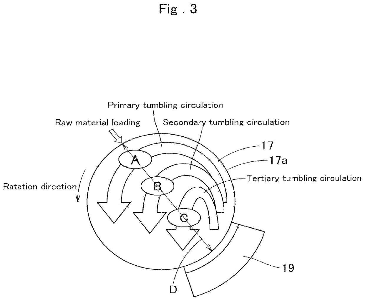
[0119]An Example carried out along with Comparative Examples to confirm the effects of the present invention shall now be described. As the tumbling granulator, that including a pan type rotating plate with an inner diameter of 300 mm was used for the Example and Comparative Examples 1 and 2. The A zone, B zone, and C zone, which are the respective spraying zones in the rotating plate 15, were set as shown in FIG. 3 described above and a width of each spraying zone was set to 50 mm.

[0120]The raw material and chemical agents used and specifications thereof are as follows.

[0121]1) Raw Materials

[0122]Calcined alumina fine powder (low soda alumina) ⋅⋅⋅ Mean particle diameter: 2.5 μm; Na2O: 0.08%; specific surface area: 1.4 g / m2

[0123]Activated alumina ⋅⋅⋅ Mean particle diameter: 1.5 μm; Na2O: 0.45%; specific surface area: 1.5g / m2

[0124]2) Chemical Agents

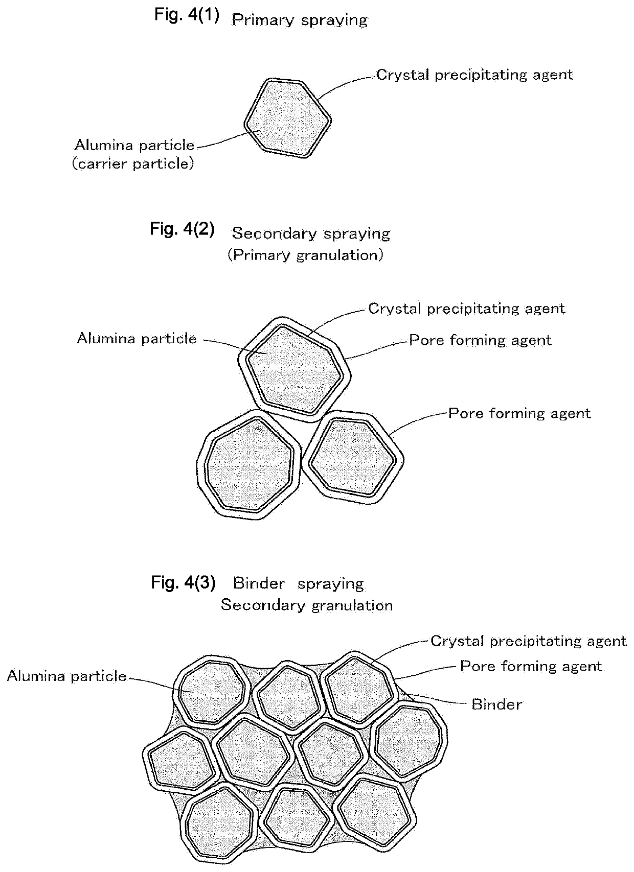
[0125]Crystal precipitating agent (primary spray liquid) ⋅⋅⋅ 30% aqueous solution of aluminum lactate

[0126]Pore forming agent (secondar...

Example

EXAMPLE

[0129]To a rotating plate adjusted to a tilt angle of 55° and rotating at 25 min−1, 100 g of the low soda alumina, which is the raw material, is loaded from a raw material loading portion (above the A zone), and thereafter the rotating plate is started and the rotational speed and the tilt angle are adjusted so that appropriate tumbling circulation occurs with the raw material powder. The adjustment ranges were set to 25 to 35 min−1 for the former and to 55 to 62° for the latter.

[0130]1) At the A zone, the primary spray liquid was sprayed onto the raw material undergoing the primary tumbling circulation. In this process, spraying was performed with spraying pressure and spraying amount per unit time being adjusted so that the droplet diameter will be 10 μm. The total spraying amount in this process was set to 20 parts with respect to 100 parts of the raw material. In the present Example, the spray amount per unit time was set to 2.5 parts / min and therefore the total spraying ...

Example

Comparative Example 1

[0137]In the Example described above, 100 g of activated alumina (Na2O: 0.45%; median particle diameter: 1.5 μm; specific surface area: 200 m2 / g) were loaded as the raw material, and while subjecting the raw material to tumbling circulation under the same conditions and without performing the primary and secondary spray coatings, the binder (10% aqueous solution of PVAL) was sprayed at the A zone at a spraying amount per unit time of 25 g (2.5 g as solids) / min for a total time of 4 min to attain a total spraying amount of 100 g (10 g as solids).

[0138]The wet granulated body prepared thus was fired under the same conditions as in the Example.


PUM

PropertyMeasurementUnit
Diameteraaaaaaaaaa
Diameteraaaaaaaaaa
Diameteraaaaaaaaaa

Abstract

A porous fired granulated body is formed by consolidating numerous alumina particles to each other while letting mainly interconnected pores remain in network form across an entire cross section of a granulated body particle. The pores have an inner diameter controlled by a droplet diameter of a pore forming agent and have numerous precipitated alumina crystals formed on inner surfaces thereof. Manufacture is performed by spraying the pore forming agent (emulsion) onto a raw material to form a coating layer of the pore forming agent on a surface of the raw material particle and controlling the inner diameter of the pores. A porous fired granulated body of alumina having a high specific surface area and having higher strength for the same specific surface area can thus be provided by a simple manufacturing method.

Description

[0001]This Application is a Division of U.S. patent application Ser. No. 15 / 546,372 filed on Jul. 26, 2017, which is National Stage Entry of PCT Application No. PCT / JP2015 / 052795 filed on Feb. 2, 2015. The entire contents of these applications are incorporated herein by reference in their entirety.FIELD OF THE ART[0002]The present invention relates to a porous fired granulated body and a method for manufacturing the same.[0003]Here, “fired” refers to consolidating a granulated body, constituted of numerous ceramic particles, as represented by alumina particles, by high temperature processing at not less than a temperature (for example, of 700° C.) at which precipitated alumina crystals are obtained inside pores. However, complete sintering, by which the pores become completely blocked, is not included.[0004]In the description that follows, “%” and “parts,” which indicate units of mixing, signify “% by mass” and “parts by mass” unless noted otherwise.[0005]Also, the respective charac...

Claims


Application Information

Patent Timeline
IPC IPC(8): C04B38/00C04B38/06C04B35/634C04B35/626C04B35/111
CPCC04B38/067C04B35/62695C04B35/62685C04B38/0051C04B38/009C04B2111/0081C04B2235/3217C04B2235/3218C04B35/634C04B35/111C04B2235/60C04B38/0058
Inventor TAKAHASHI, AKIRASHIMOSATO, JUNYANAKAMURA, TAKAHIKOTAMURA, NORIYUKI
Owner ITOCHU CERATECH
Why Eureka
Try Eureka