

Ammonia decomposition facility, gas turbine plant equipped with same, and ammonia decomposition method
- Summary
- Abstract
- Description
- Claims
- Application Information
AI Technical Summary
Benefits of technology
Problems solved by technology
Method used
Image

Examples
first embodiment
[0040]A gas turbine plant according to a first embodiment will be described with reference to FIG. 1 to FIG. 5.
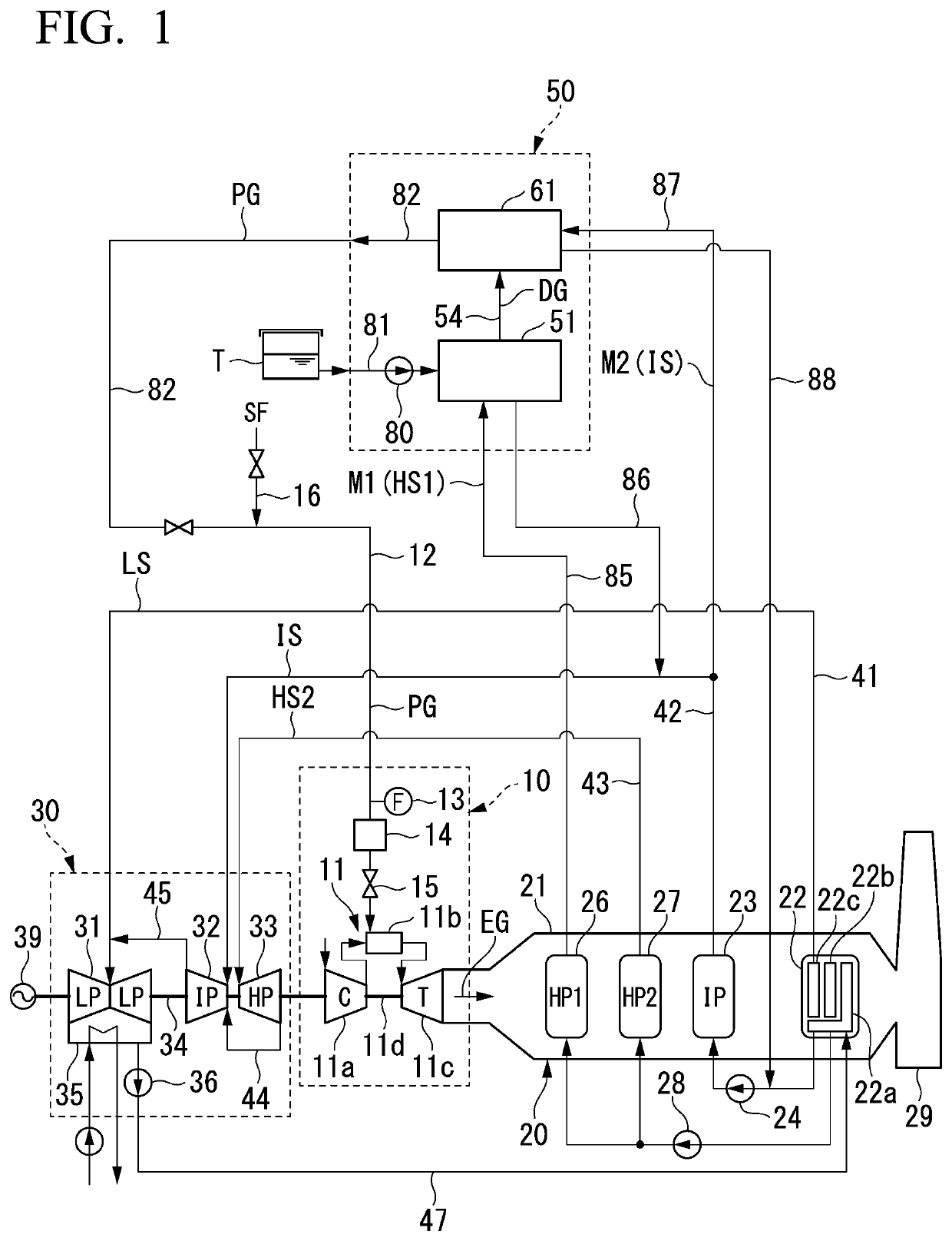
[0041]As shown in FIG. 1, the gas turbine plant of the present embodiment includes a gas turbine facility 10, an exhaust heat recovery boiler 20, a steam turbine facility 30, and an ammonia decomposition facility 50.
[0042]The gas turbine facility 10 includes a gas turbine 11, a fuel line 12 that guides a fuel to the gas turbine 11, a flow meter 13 that detects a flow rate of a fuel that flows through the fuel line 12, a preheater 14 that preheats a fuel which flows through the fuel line 12, and a fuel control valve 15 that controls a flow rate of a fuel that is supplied to the gas turbine 11.
[0043]The gas turbine 11 includes an air compressor 11a that compresses air to generate compressed air, a combustor 11b that combusts a fuel in the compressed air to generate a combustion gas, and a turbine 11c that is driven by the combustion gas. The combustor 11b has a structure that...
second embodiment
[0108]A gas turbine plant according to a second embodiment will be described with reference to FIG. 6.
[0109]In the gas turbine plant according to the first embodiment, when the gas turbine 11 starts, the start-up fuel SF such as natural gas is used, and only the processed gas PG is used during a steady operation after startup. On the other hand, in the gas turbine plant in the present embodiment, the natural gas NG is used not only during startup but also during a steady operation. However, in the gas turbine plant of in the present embodiment, the processed gas PG is mixed with the natural gas NG during the steady operation, and this mixed gas is used as a fuel.
[0110]As in the gas turbine plant in the first embodiment, as shown in FIG. 6, the gas turbine plant in the present embodiment also includes the gas turbine facility 10, the exhaust heat recovery boiler 20, the steam turbine facility 30, and the ammonia decomposition facility 50.
[0111]The configuration of the gas turbine fac...
modification example
[0127]In the above embodiments, the gas turbine rotor 11d and the steam turbine rotor 34 are connected. However, the gas turbine rotor 11d and the steam turbine rotor 34 may not be connected. In this case, a generator is connected to each of the gas turbine rotor 11d and the steam turbine rotor 34.
[0128]The steam turbine facility 30 in each of the above embodiments includes three types of the steam turbines 31, 32, and 33 in which inflow steam pressures are different from each other. However, the steam turbine facility may include only one type of steam turbine as the steam turbine. In this case, the steam generation system of the exhaust heat recovery boiler need only include one type of steam generation system as a steam generation system that generates steam for driving the steam turbine.
[0129]In the above embodiments, the heating medium sent to the ammonia decomposer 53 is water vapor from the exhaust heat recovery boilers 20 and 20a. However, any medium may be used as long as h...
PUM
 Abstract
Description
Claims
Application Information