Ventilated housing and assembly

a technology of ventilated housing and housing housing, which is applied in the direction of combustion treatment, modification using gaseous coolants, light and heating apparatus, etc., can solve the problems of loss of potential revenue, the inability of cable management systems to meet the requirements of industry standards for both front and rear dressing of cables, and the overheating of the upper unit, etc., to achieve the effect of saving vertical space, reducing requirements, and reducing requirements

Inactive Publication Date: 2007-11-15
ALCATEL LUCENT SAS
View PDF12 Cites 6 Cited by
  • Summary
  • Abstract
  • Description
  • Claims
  • Application Information

AI Technical Summary

Benefits of technology

[0013] Advantageously, the slope of the upper and lower air barriers in aspects of the present invention allows for saving of vertical space over the prior art convection cooled systems when ventilated housings are stacked. The second part of the upper air barrier of one stacked housing may be at a level at or above the level of the first part of the lower air barrier of the housing above the one stacked housing. Thus, there may be an vertical overlap of the air space between the upper and lower units and the air barriers of the units. Alternatively, the same amount of total space may be used as with traditional stacked systems while achieving a greater air space between each housing. An improved convection cooled product reduces the requirements for forced air systems, which require fan and filter maintenance.

Problems solved by technology

If two such units are stacked without a space between them, the hot air radiating from the bottom unit heats up the air in the cool air intake of the upper unit possibly resulting in the upper unit overheating.
Additionally, the cable management systems available do not always accommodate both front and rear dressing of cables within industry standards.
One solution is to leave one rack unit of space between units to overcome this preheating and allow for proper fiber management, but this arrangement takes up valuable space and therefore possibly results in loss of potential revenue.
This solution also takes up additional vertical rack space with associated revenue loss.
Units cooled using forced air solutions cost more, take up more rack space and require more maintenance than convection cooling solutions.
The fans in such forced air systems are bulky and require regular maintenance.
Furthermore, if the fan is not working, the unit can not be operated.

Method used


Image

  • Ventilated housing and assembly
  • Ventilated housing and assembly
  • Ventilated housing and assembly

Examples


Embodiment Construction

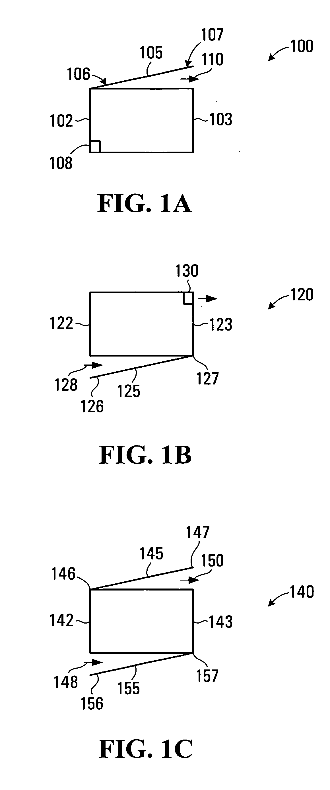
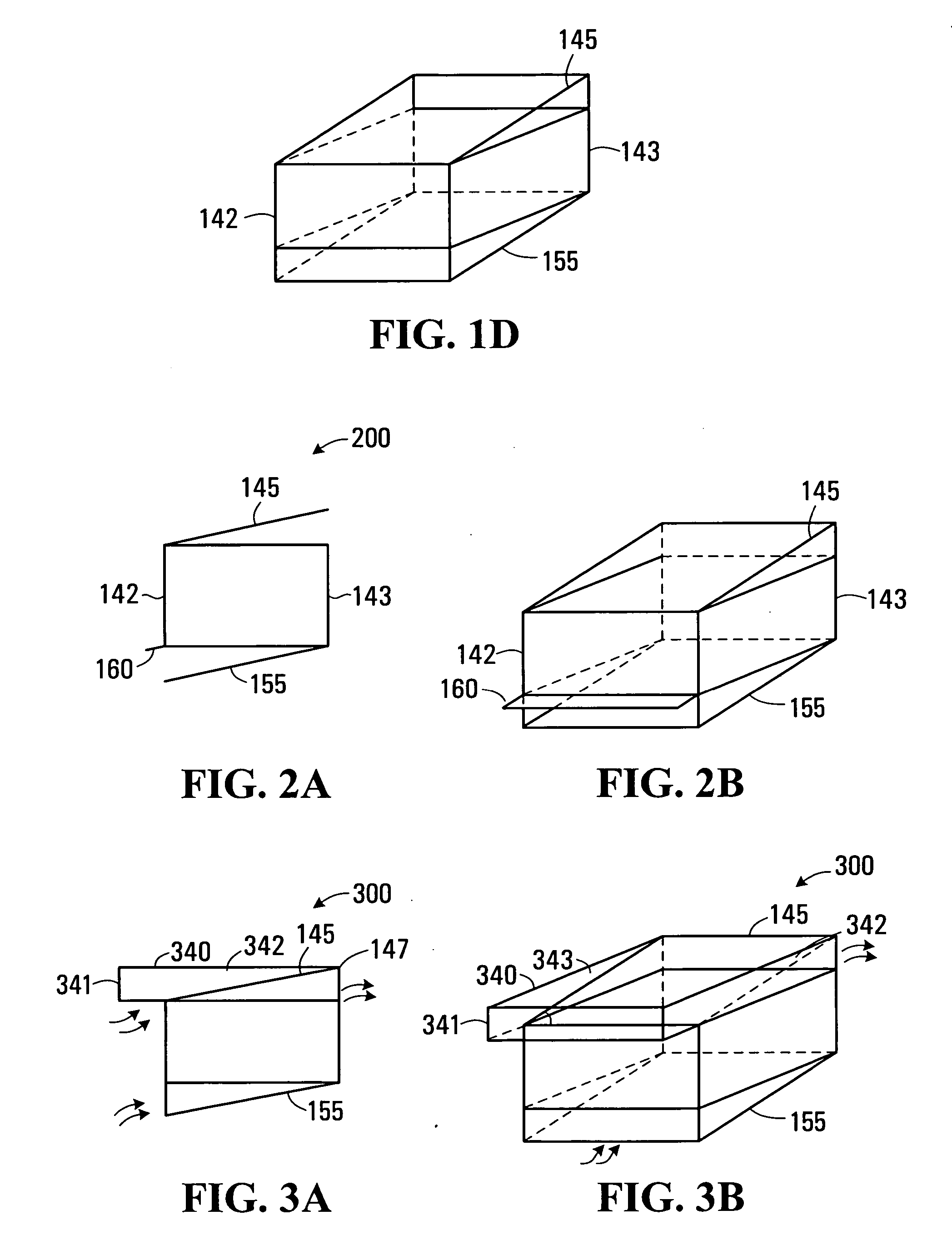
[0030] For ease of reference, the same reference numerals are used to refer to parts that perform the same function in each embodiment.

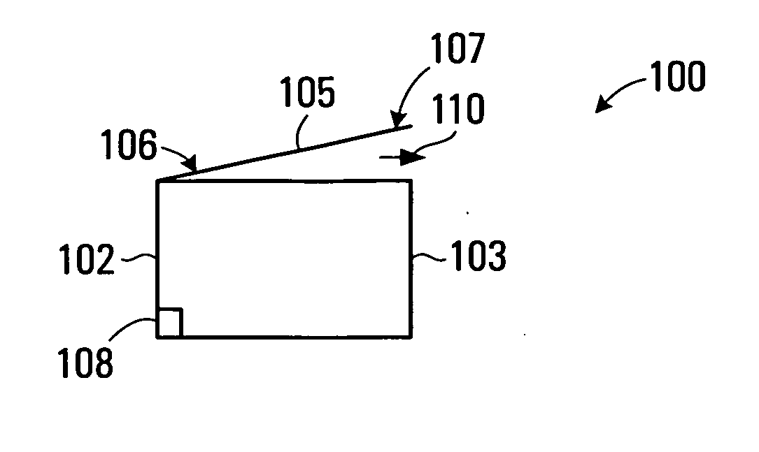
[0031] Referring to FIG. 1A, one embodiment of a ventilated housing 100 for accommodating one or more component comprises opposed first and second spaced-apart end portions 102 and 103. An upper air barrier 105 extends at least partially between the first and second end portions 102 and 103 and has an upper surface. In some embodiments, the upper air barrier 105 defines an upper surface of the ventilated housing 100. In other embodiments, the housing also comprises a louver structure or a perforated support (not shown) above the upper air barrier 105. The upper air barrier 105 limits upward movement of air inside the housing 100. A first part 106 of the upper air barrier 105 proximate the first end portion 102 is positioned at a level below the level of a second part 107 of the upper air barrier 105 proximate the second end portion 103. An inlet 108...


PUM


Abstract

A ventilated housing for accommodating one or more components comprises opposed first and second-spaced apart end portions. An air barrier extends at least partially between the first and second end portions for limiting movement of air inside the housing and defining an upper or lower surface of the housing. A first part of the air barrier proximate the first end portion is positioned at a level below the level of a second part of the air barrier proximate the second end portion. An inlet is defined for admitting air into the housing and an outlet is defined for discharging air from the housing. An ventilated housing assembly comprises first and second housings with an angled space between a lower air barrier of the first housing and an upper air barrier of the second housing.

Description

FIELD OF THE INVENTION [0001] The present invention relates to ventilated housings and ventilated housing assemblies. BACKGROUND [0002] Existing convection cooled units for rack-mounted communication equipment typically leave a horizontal space between shelves for an air cushion and / or baffle units and / or cable management units. Typically, convection cooled units have a box-shaped cool air intake on the bottom and a box-shaped hot air exhaust on the top. If two such units are stacked without a space between them, the hot air radiating from the bottom unit heats up the air in the cool air intake of the upper unit possibly resulting in the upper unit overheating. [0003] Cable management in systems, such as telecommunication systems, is normally single-function and requires additional vertical space to ensure that the cables do not hinder the air intake and outlets of convection cooled units within the systems. For example, it is desirable to avoid passing the cables in front of the co...

Claims


Application Information

Patent Timeline
Patent Type & Authority Applications(United States)
IPC IPC(8): E04F17/02
CPCH05K7/20009
Inventor LETOURNEAU, FABIENSCHMIDT, BEVINBUNDZA, NICHOLAS ADAM
Owner ALCATEL LUCENT SAS
Why Eureka
Try Eureka