
Memory diagnostic method

Inactive Publication Date: 2007-11-15
TOSHIBA STORAGE DEVICE CORP
View PDF12 Cites 21 Cited by
  • Summary
  • Abstract
  • Description
  • Claims
  • Application Information

AI Technical Summary

Benefits of technology

[0012] An object of the present invention, therefore, is to write and read massive amounts of data at once by using hardware and thereby increase the speed of memory diagnosis that was conventionally performed by a microprocessor on the basis of firmware, and to perform other processes in parallel with the memory diagnosis by sharing the microprocessor. In addition to this object, another object of the present invention is to improve the reliability of memory diagnosis by conducting diagnosis on the entire memory area.
[0022] According to the memory diagnostic function of the present invention, the diagnostic data stored in each storage memory is written to and read from the SDRAM by means of hardware, and is further compared with different diagnostic data, whereby the diagnosing time can be reduced and diagnosis can be conducted on all areas of the SDRAM. Also, memory diagnosis can be performed without occupying the microprocessor, thus memory diagnosis can be performed in parallel with other operations.

Problems solved by technology

Due to limitations of time required for the hard disk device to reach the available state, it was impossible to conduct diagnosis on all memory areas, thus the memory areas were divided, whereby the diagnosis was conducted only on some memory areas.
In the above method, reading and writing 2 bytes of diagnostic data are performed on each memory area on the basis of the firmware in which the memory diagnosis is implemented by the microprocessor, thus the processing speed of the memory diagnosis is slow.
Moreover, since the diagnosis is conducted only on some of the memory areas, this memory diagnosis is less reliable than the case where the diagnosis is conducted on all memory areas.

Method used


Image

  • Memory diagnostic method
  • Memory diagnostic method
  • Memory diagnostic method

Examples


first embodiment

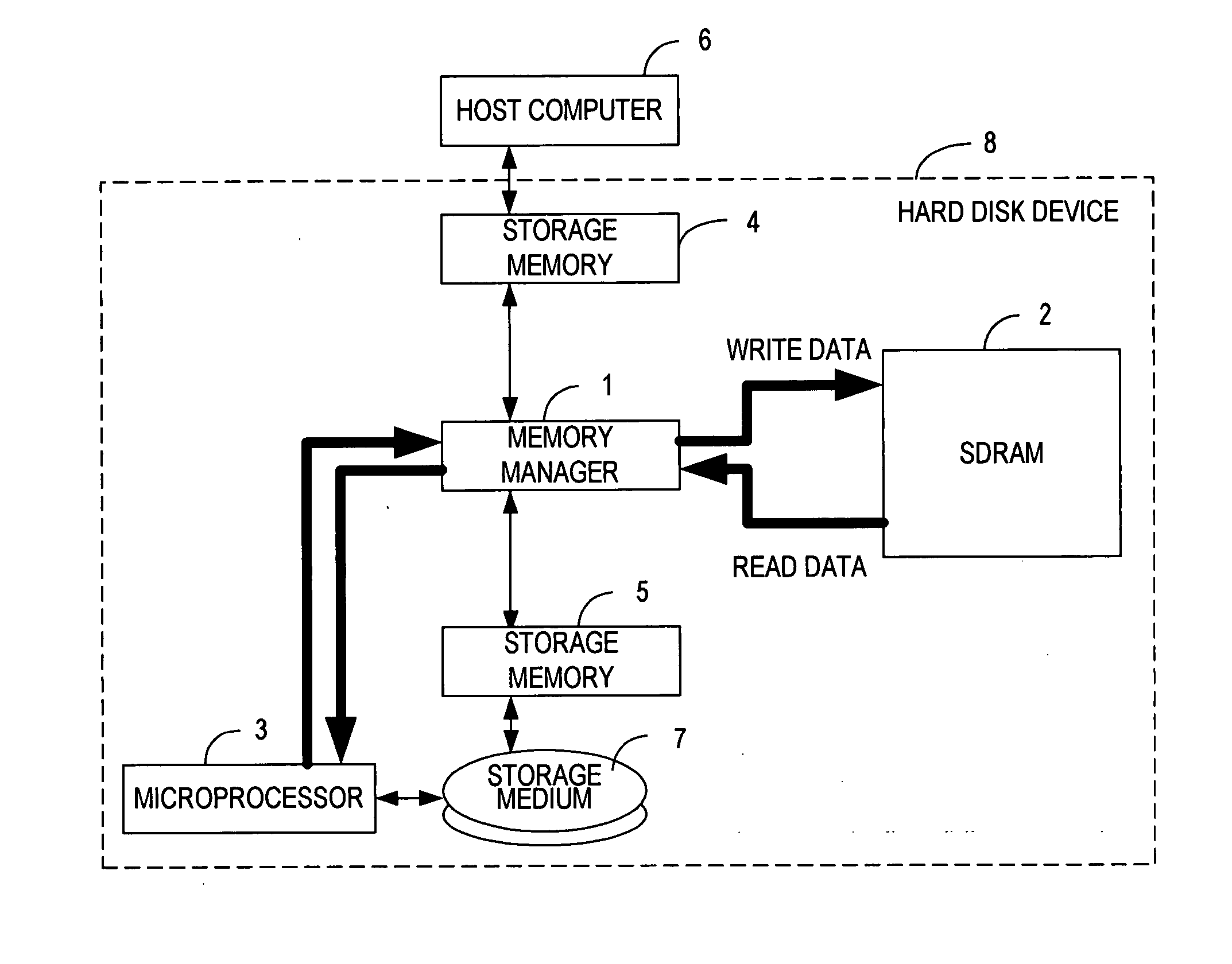
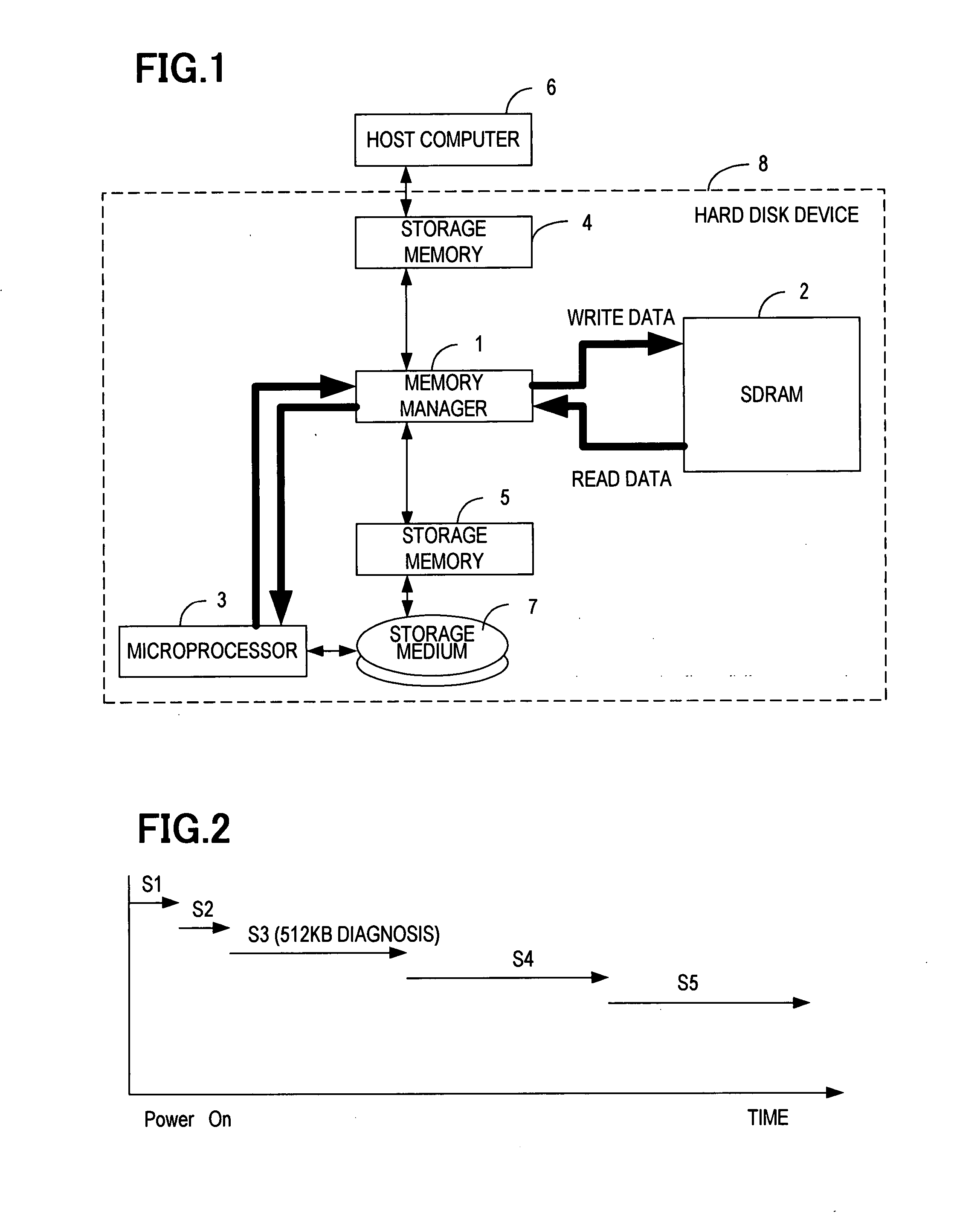
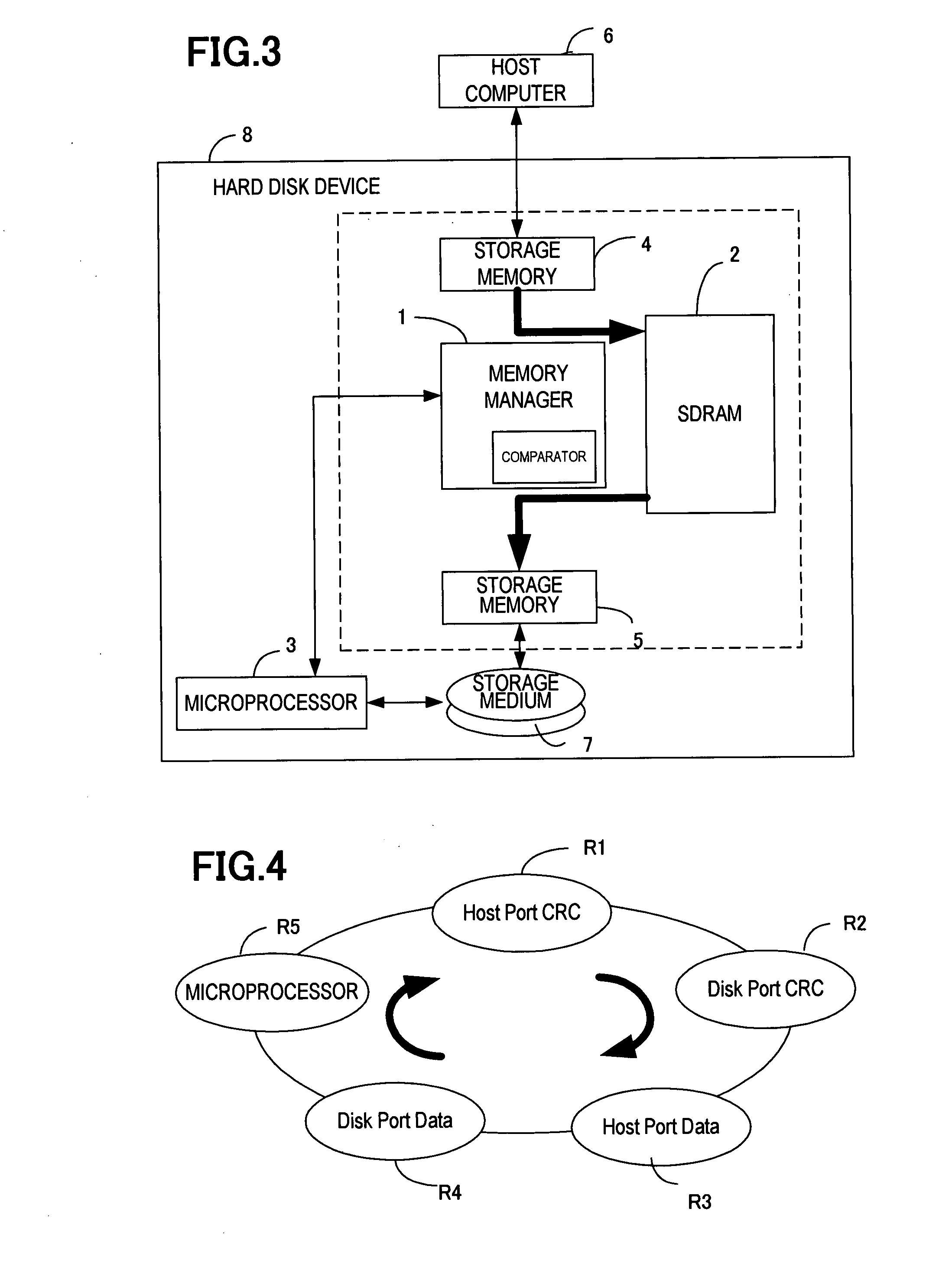
[0034]FIG. 3 is a configuration diagram of a hard disk device having a memory diagnostic function of the present invention. A memory manager 1 for managing writing and reading of data to and from an SDRAM 2 is connected to a host computer 6, storage medium 7, and microprocessor 3 managing the entire hard disk device. A first storage memory 4 is disposed between the memory manager 1 and the host computer 6. A second storage memory 5 is disposed between the memory manager 1 and the storage medium 7. In the present embodiment the section surrounded by the dashed line shown in FIG. 3 is a memory diagnostic apparatus.

[0035] It should be noted in the first embodiment of the present invention that the first storage memory 4 and the second storage memory 5 are each configured from a FIFO. Normally, the hard disk device has: the SDRAM 2 for temporarily accumulating write data and read data; a FIFO for complementing a difference in data transfer speed between the storage medium 7 and the SDRA...

second embodiment

[0044]FIG. 6 is a configuration diagram of a hard disk device having a memory diagnostic function according to the present invention. The memory manager 1 for managing writing and reading of data to and from the SDRAM 2 is connected to the host computer 6, storage medium 7, and microprocessor 3 managing the entire hard disk device. The first storage memory 4 is disposed between the memory manager 1 and the host computer 6, and the second storage memory 5 is disposed between the memory manager 1 and the storage medium 7. In the present embodiment the section surrounded by the dashed line shown in FIG. 6 is a memory diagnostic apparatus.

[0045] It should be noted in the second embodiment of the present invention that the first storage memory 4 and the second storage memory 5 are each configured from a FIFO. Normally, the hard disk device has: the SDRAM 2 for temporarily accumulating write data and read data; a FIFO for complementing a difference in data transfer speed between the stora...


PUM


Abstract

A storage device can reduce time for diagnosis and allows the diagnosis to be conducted on the entire area of a memory. The storage device includes a temporary memory that temporarily stores for a storage medium, data written to and / or read from a host system by the storage medium; a memory manager that manages writing and / or reading performed on the temporary memory; a first storage memory that complements a difference in processing speed of writing and / or reading between the host system and the temporary memory; and a second storage memory that complements a difference in processing speed of writing and reading between the storage medium and the temporary memory. The memory manager has a comparator, which compares the diagnostic data stored in the first storage memory with the read data stored in the second storage memory, and determines that there is an abnormality if a comparison result is inconsistent.

Description

CROSS REFERENCE TO RELATED APPLICATIONS [0001] This application is a continuation of International Application No. PCT / JP2004 / 19600, filed on Dec. 28, 2004, now pending, herein incorporated by reference.TECHNICAL FIELD [0002] The present invention relates to a storage device having a memory diagnostic function, and a memory diagnostic method in the storage device. BACKGROUND ART [0003] At the present day, the information processors such as computers are equipped with various types of memories. Diagnosis is conducted on these memories to determine whether data can be written, held and read properly. As one such diagnostic method, there is the technology described in Japanese Unexamined Patent Publication No. H7-271679 wherein the right to possess a bus for accessing a memory is passed from a microprocessor to a diagnosis start / stop circuit every time diagnosis is performed on one address, to reduce the occupation of the microprocessor. [0004] As such memory, there is an SDRAM which i...

Claims


Application Information

Patent Timeline
IPC IPC(8): G11C29/00
CPCG06F11/0727G06F11/0751G06F11/073
Inventor OYAMADA, MAOKO
Owner TOSHIBA STORAGE DEVICE CORP
Learn More