Method of measuring the size of a leak in a pneumatic air circuit and a related device

Inactive Publication Date: 2012-10-04
EUTECTIC SOLUTIONS
View PDF6 Cites 13 Cited by
  • Summary
  • Abstract
  • Description
  • Claims
  • Application Information

AI Technical Summary

Benefits of technology

[0035]By establishing the exact size of the leak (or leaks) and comparing the leak size with the best potential performance of the ULD, the appropriate approach to locating the leak is much clearer. Using this method, the heavy equipment mechanic will eliminate time wasted on leaks that are impossible to find with the ULD.
[0040]Note that the current invention has the ability to emulate any size leak via its built in test port to verify the ULD's capability, adding confidence in the ULD to the process.
[0044]The total time to hook up the device of the current invention, locate the leaks then retest for final results will vary from 30 to 40 minutes. This predicts the time required and reduces the potential diagnostic time from 4 hours to less than 1 hour. Further, the results are guaranteed and both the mechanic and the truck owner are winners.
[0045]Note that repairing air brake leaks reduces compressor cycle times, protecting it from premature failure, improves fuel consumption, less engine load and reduces harmful exhaust emissions, as the engine is not working harder to drive the compressor longer.

Problems solved by technology

However, Oswald does not disclose using two flow meters in series to measure air flow when both pressurizing and evaluating a ULD test device.
Further, none of the devices in the prior art provide a simple portable device designed for this purpose.
While commercial equipment exists to accurately measure system recovery times (for certification purposes), this type of equipment does not specifically address the size of the system's leaks.

Method used


Image

  • Method of measuring the size of a leak in a pneumatic air circuit and a related device
  • Method of measuring the size of a leak in a pneumatic air circuit and a related device
  • Method of measuring the size of a leak in a pneumatic air circuit and a related device

Examples


Embodiment Construction

The Operation of an Embodiment of the Invention

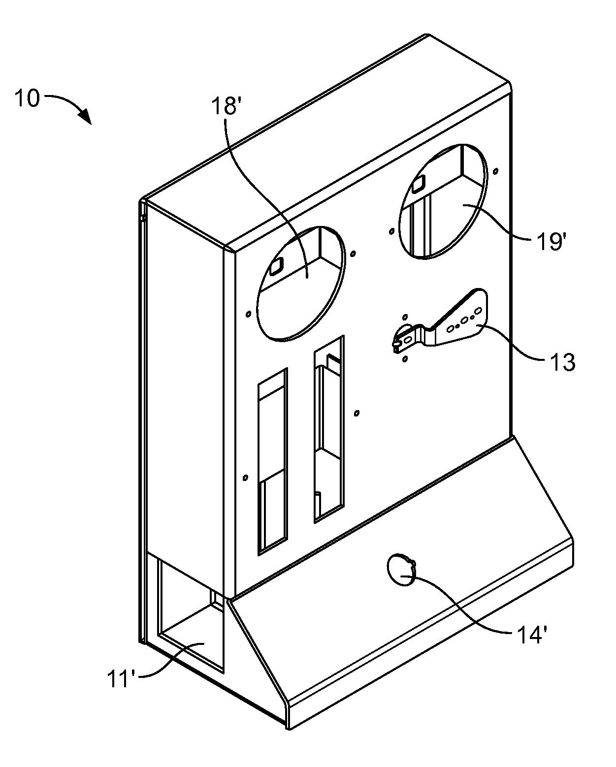
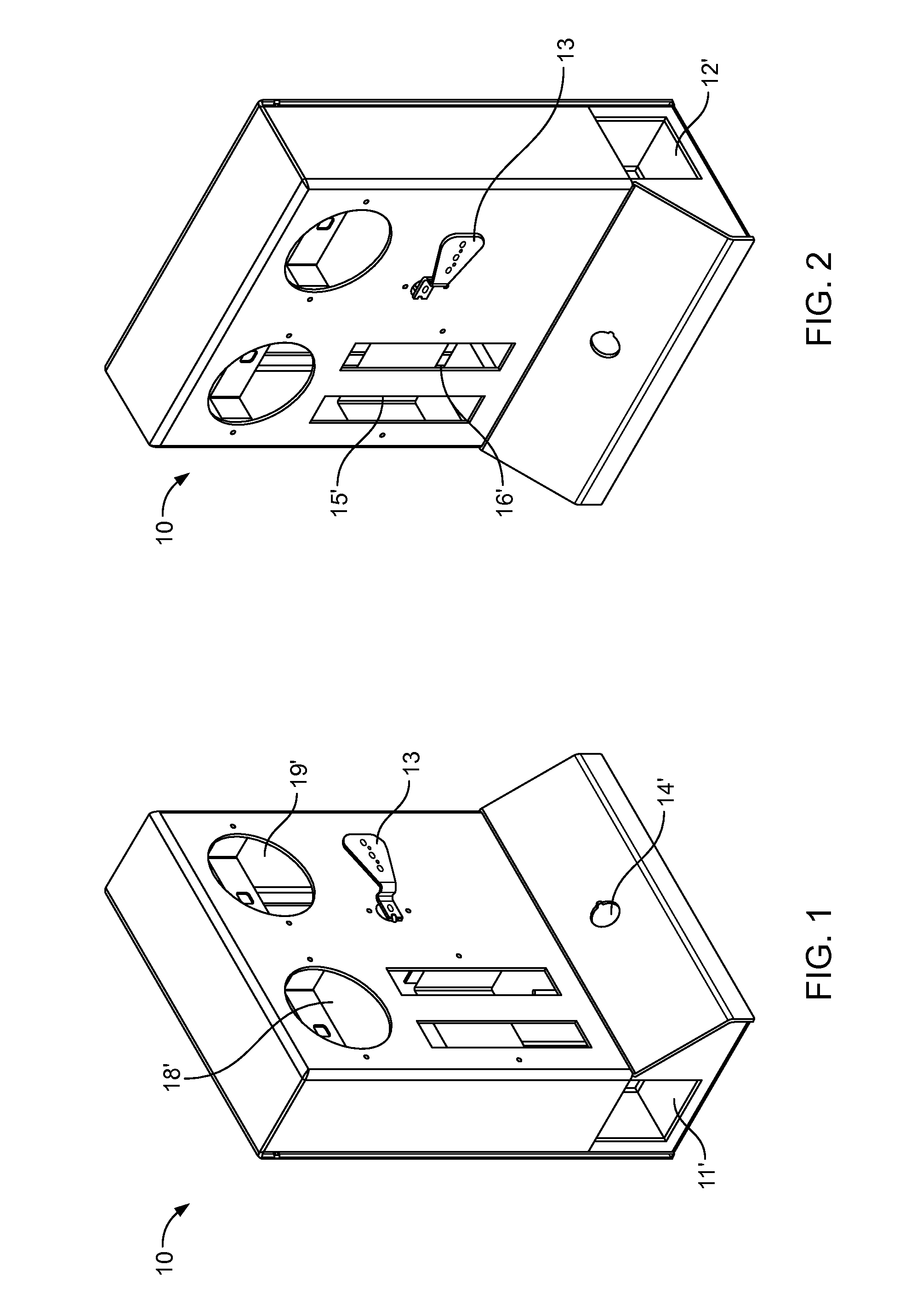
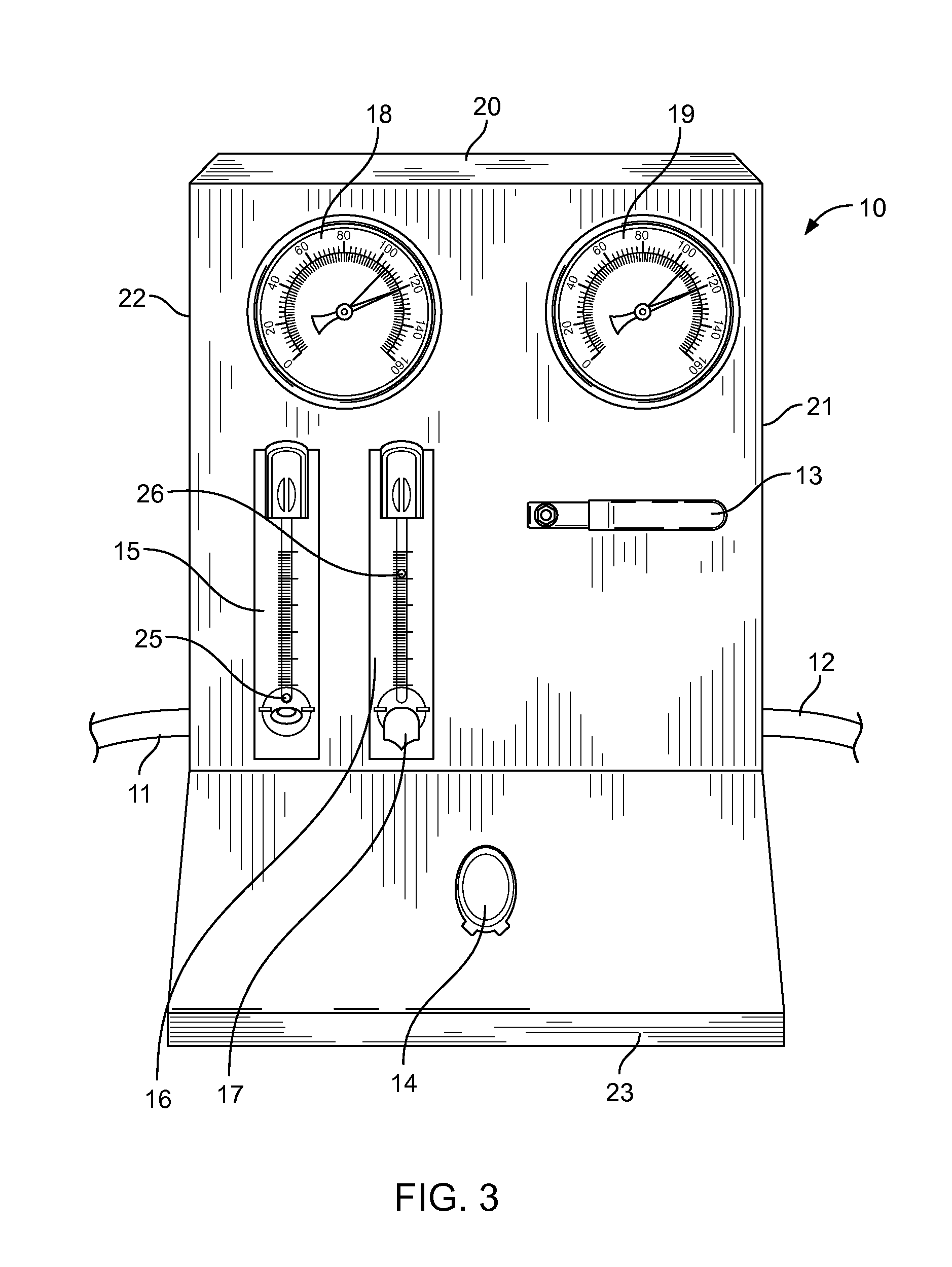
[0075]Hook up: the air line into the truck's dryer is removed at the dryer and the air brake solution test hose is hooked into the dryer. The shop's air supply is plugged into the air brake solution.

[0076]Set target pressure: using the pressure regulator, the target test pressure is set, usually 100 psi. This is reflected on the target pressure gauge.

[0077]Reset to bypass mode: the reset valve is cycled on / off to ensure the air brake solution is in its bypass mode. This bypasses the air flow meters to speed up the fill process.

[0078]The fill process: the lock 'n load lever is turned to the load position and the system begins to fill. As the air brake system begins to fill, its pressure is shown on the system pressure gauge.

[0079]At this point there is a wait time for the two pressure gauges to equalise. If the air brake system is empty it will take 7 to 10 minutes (depending on capacity) to fill the system.

[0080]Shift to airflow meters:...


PUM


Abstract

A leak detecting device comprising: a housing with gas inlet, a gas outlet, at least one pressure gauge for measuring the gas pressure supplied to the tested system, at least one flow meter for measuring the flow of the gas from the device to the tested system, at least one flow control valve to vary the gas flow through the device, an operating valve for permitting the flow of the gas from the device into the system to be tested. When said device is utilized, the inlet is attached to a pressure generating apparatus, the outlet is attached to the system to be tested, said pressure gauge showing the system testing pressure, and the flow meter indicates the flow of the gas through the device and the system being tested, thereby indicating the existence of any leakage and quantifying the total size of the leakage.

Description

CROSS-REFERENCE TO RELATED APPLICATIONS[0001]This application claims priority to U.S. Provisional Application No. 61 / 469,347 filed on Mar. 30, 2011, the entire contents of which are incorporated herein by this reference.FIELD OF THE INVENTION[0002]This invention relates to a device and method used for determining the size of an air leak in a pneumatic circuit and for establishing the effectiveness of an ultrasonic leak detection device.BACKGROUND OF THE INVENTION[0003]Compressed air is required for stopping a vehicle as well as allowing it to move. An air brake system that has leaked all of its compressed air, will by default, lock up all of the wheels. Generally, the system needs to be charged to 60 psi or higher to unlock the wheels.[0004]An air brake system's operating pressure range is generally between 90 and 125 psi. When the system pressure drops to the lower end of the range, it is topped up by the compressor and associated valving. It's normal for air pressure to fluctuate ...

Claims


Application Information

Patent Timeline
IPC IPC(8): G01M3/24G01M3/28
CPCG01M3/007G01M3/26G01M3/24
Inventor FINLAY, GEOFF
Owner EUTECTIC SOLUTIONS
Why Eureka
Try Eureka