Gas Reformulating System Using Plasma Torch Heat

a plasma torch heat and gas reformulating technology, applied in the details of gasification processes, combustion processes, fuel cells, etc., can solve the problems of insufficient treatment of prior systems and processes, less desirable disposal of waste materials by incineration,

Active Publication Date: 2007-11-22
PLASCO CONVERSION TECH INC
View PDF95 Cites 91 Cited by
  • Summary
  • Abstract
  • Description
  • Claims
  • Application Information

AI Technical Summary

Benefits of technology

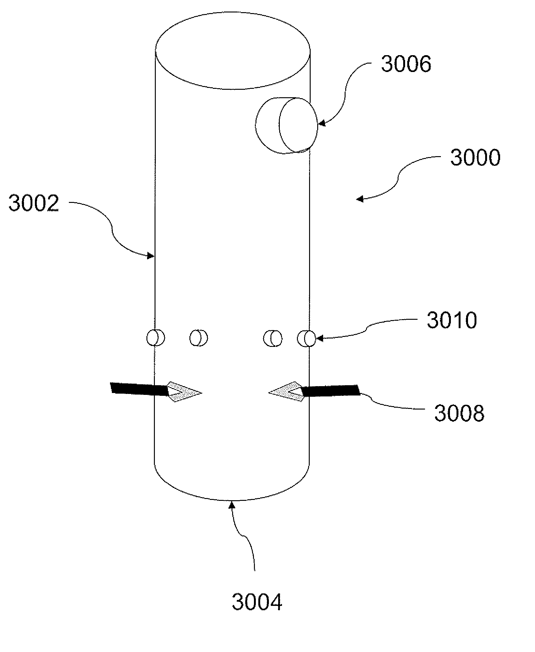
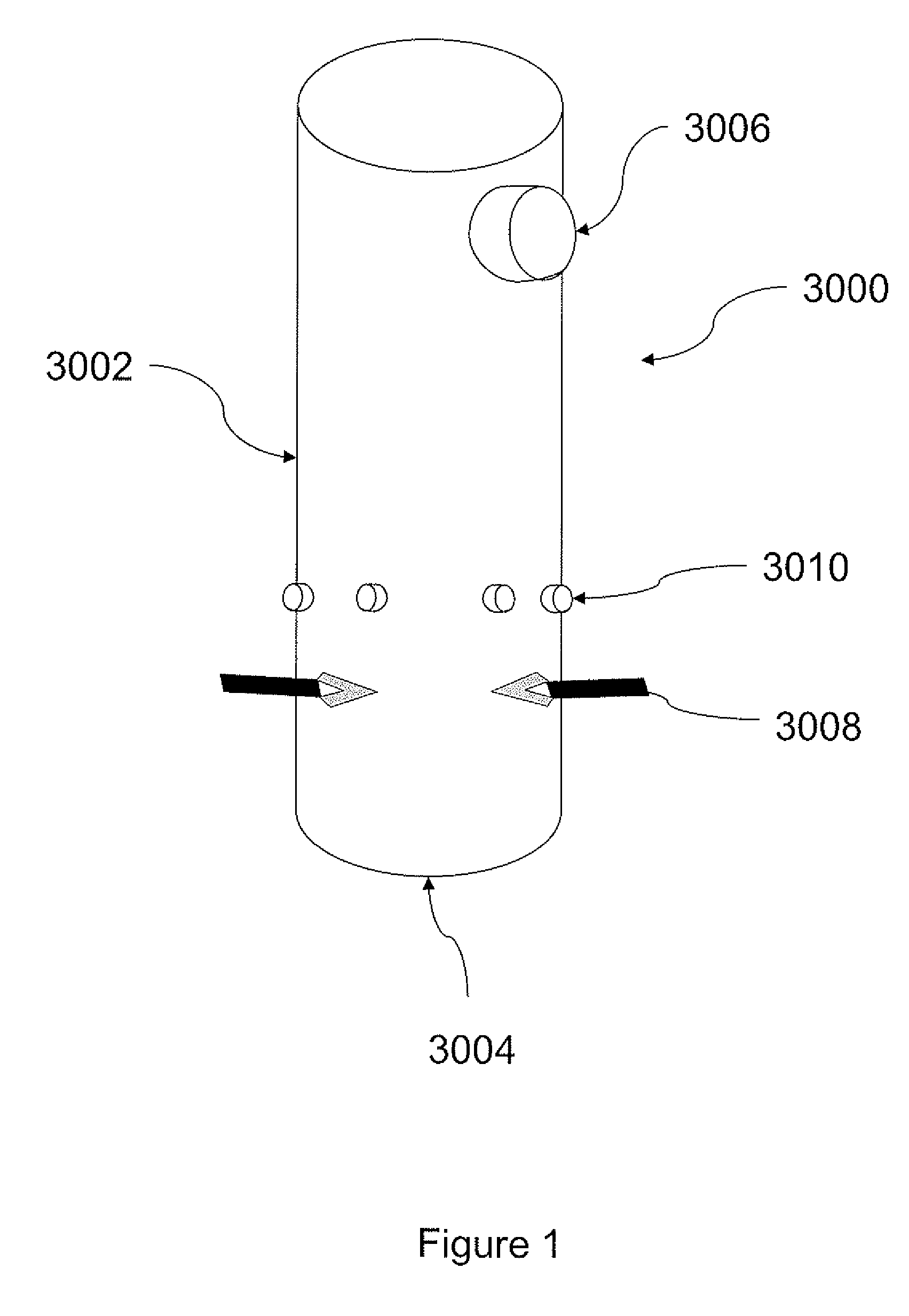
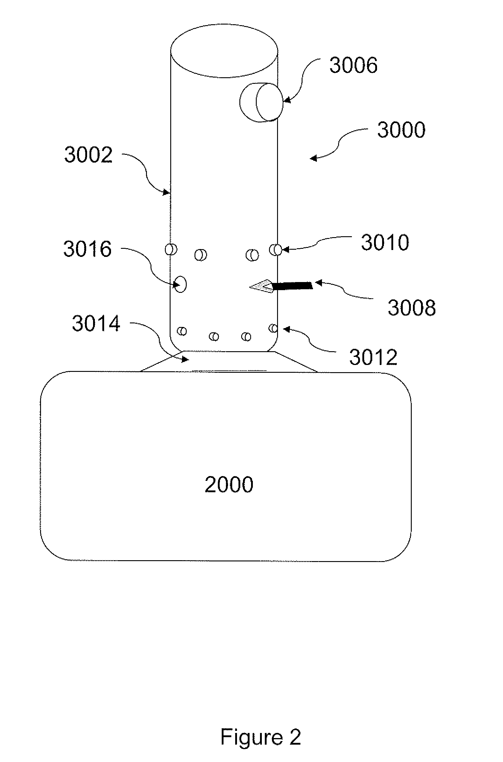
[0020] An object of the present invention is to provide a gas refining system using plasma torch heat. In accordance with an aspect of the invention, there is provided a system for reformulating of an input gas from a gasification reaction to a reformulated gas of defined chemical composition comprising a refractory-lined cylindrical chamber having a first end and a second end, said chamber comprising an input for receiving the input gas positioned at or near the first end of the chamber; an output for releasing the reformulated gas positioned at or near the second end of the chamber; one or more oxygen source(s) inputs in fluid communication with the chamber; and one or more plasma torches; wherein said plasma torch(es) heat the chamber and the input gas is thereby converted to reformulated gas.
[0021] In accordance with another aspect of the invention, there is provided a method for reformulating an input gas from a gasification reaction into a reformulated gas, comprising the steps of delivering the input gas at an inlet of a refractory-lined chamber; injecting an oxygen source into the chamber; torch heating the chamber with one or more plasma torches, and thereby producing the reformulated gas.
[0022] This invention provides a gas reformulating system for the reformulating of input gas derived from gasification of carbonaceous feedstock into reformulated gas of a defined chemical composition. In particular, the gas reformulating system uses torch heat from a plasma torch to dissociate the gaseous molecules thereby allowing their recombination into smaller molecules useful for downstream application, such as energy generation. The system may also comprise gas mixing means, process additive means, and a control system with one or more sensors, one or more process effectors and computing means to monitor and / or regulate the reformulating reaction.

Problems solved by technology

It is becoming less desirable to dispose of waste material by incineration because of the extreme waste of fuel in the heating process and the further waste of disposing, as a residual waste, material that can be converted into a useful syngas and solid material.
The gas produced during the gasification of carbonaceous feedstock is usually very hot but may contain small amounts of unwanted compounds and requires further treatment to convert it into a useable product.
Prior systems and processes have not adequately addressed the problems that must be dealt with on a continuously changing basis.

Method used


Image

  • Gas Reformulating System Using Plasma Torch Heat
  • Gas Reformulating System Using Plasma Torch Heat
  • Gas Reformulating System Using Plasma Torch Heat

Examples


example

[0205] FIGS. 14 to 18 show a converter incorporating an embodiment of the GRS comprising the gas reformulating chamber shown in FIG. 5.

[0206] The gasifier 2200 comprises a refractory-lined horizontally-oriented stepped-floor gasification chamber 2202 having a feedstock input 2204, gas outlet 2206 and a solid residue outlet 2208. The gasification chamber 2202 is a refractory-lined steel weldment having a stepped floor with a plurality of floor levels 2212, 2214, 2216.

[0207] The solid residue outlet is equipped with an ash extractor comprising an extractor screw 2209 which will pull the ash out of the gasifier and feed it into an ash conveyor system.

[0208] Each step has a perforated floor 2270 through which heated air can be introduced. To avoid blockage of the air holes during processing, the air hole size is selected such that it creates a restriction and thus a pressure drop across each hole. This pressure drop is sufficient to prevent waste particles from entering the holes.

[0...


PUM

PropertyMeasurementUnit
temperatureaaaaaaaaaa
pressuresaaaaaaaaaa
temperatureaaaaaaaaaa

Abstract

A method and apparatus is described for reformulating of an input gas from a gasification reaction into a reformulated gas. More specifically, a gas reformulating system having a gas reformulating chamber, one or more plasma torches, one or more oxygen source(s) inputs and control system is provided thereby allowing for the conversion of an input gas from a gasification reaction into a gas of desired composition.

Description

CROSS REFERENCE TO RELATED APPLICATIONS [0001] This application claims benefit of priority under 35 U.S.C. §119(e) from U.S. Provisional Application Ser. No. 60 / 798,075, filed May 5, 2006. This application also claims benefit of priority to International Patent Application No. PCT / CA2006 / 000881, filed Jun. 5, 2006. This application also claims benefit of priority under 35 U.S.C. §119(e) from U.S. Provisional Application Ser. No. 60 / 864,116, filed Nov. 2, 2006. This application also claims benefit of priority under 35 U.S.C. §119(e) from U.S. Provisional Application Ser. No. 60 / 911,179, filed Apr. 11, 2007. This application also claims benefit of priority under 35 U.S.C. §119(e) from U.S. Provisional Application Ser. No. 60 / 797,973, filed May 5, 2006. The contents of all of the aforementioned applications are hereby expressly incorporated by reference in their entirety and for all purposes.FIELD OF THE INVENTION [0002] This invention pertains to the field of carbonaceous feedstock ga...

Claims


Application Information

Patent Timeline
Patent Type & Authority Applications(United States)
IPC IPC(8): C10J3/00
CPCC01B3/342F23G2204/201C01B2203/0255C01B2203/061C01B2203/066C01B2203/0861C10J3/482C10J3/485C10J2200/09C10J2300/0983C10J2300/1238C10J2300/1618C10K3/008F23G5/085C01B2203/0216C01B3/363C10J3/82C10K3/003C10K3/006C10J3/20C10K1/00
Inventor TSANGARIS, ANDREASSWAIN, MARGARET
Owner PLASCO CONVERSION TECH INC
Why Eureka
Try Eureka