Clamp for use with metal bar joists and beams

Active Publication Date: 2007-11-22
MOREY DOUGLAS H
View PDF31 Cites 14 Cited by
  • Summary
  • Abstract
  • Description
  • Claims
  • Application Information

AI Technical Summary

Benefits of technology

[0008]A clamp which attaches to a metal bar joist or beam on one side and to a cross member on a reverse side is disclosed. This cross member spans the distance between two bar joists or beams and has a corresponding clamp affixed to another end of the cross member to facilitate attachment to the next bar joist or beam. For the sake of brevity, it will be understood that subsequent uses of the term “bar joist” or “joist” in this disclosure likewise refer to beams. The clamp has at least one flat length of steel or plate, made of a suitable material, such as standard A36 steel. Each plate fits under the corrugations of a typical corrugated steel roof. Each plate of the clamp is adapted to ride horizontally across a top of the bar joist, perpendicularly to the bar joist, and extend slightly over the edge of the joist. Each plate is provided with at least one elongate slot which allows a bolt with a washer attached to be inserted through the slot. A ret

Problems solved by technology

For instance, the welding may cause unintended structural damage to the remaining length of the bar joists; the welding may have to be performed from awkward angles, with limited space constraints, making the welding difficult; and the welding must be performed by skilled certified welders.
There can also be other problems associated with th

Method used


Image

  • Clamp for use with metal bar joists and beams
  • Clamp for use with metal bar joists and beams
  • Clamp for use with metal bar joists and beams

Examples


Embodiment Construction

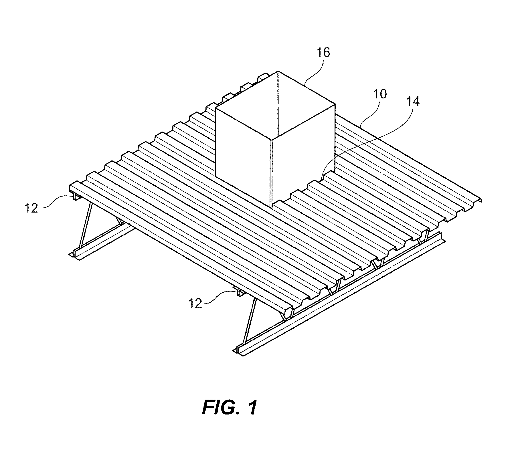
[0025]Having reference to the drawings, where like reference numbers comprise like elements, there is shown in FIG. 1 a section of a steel corrugated roof material, generally denoted by reference number 10. This roof section 10 is supported by at least two parallel metal bar joists 12. The roof section 10 rests upon these joists such that downwardly-open channels formed by corrugations of the roof material run in a direction perpendicular to the bar joists 12. An access hole 14 is shown in this roof section 10 and a structure 16 protrudes through the access hole 14.

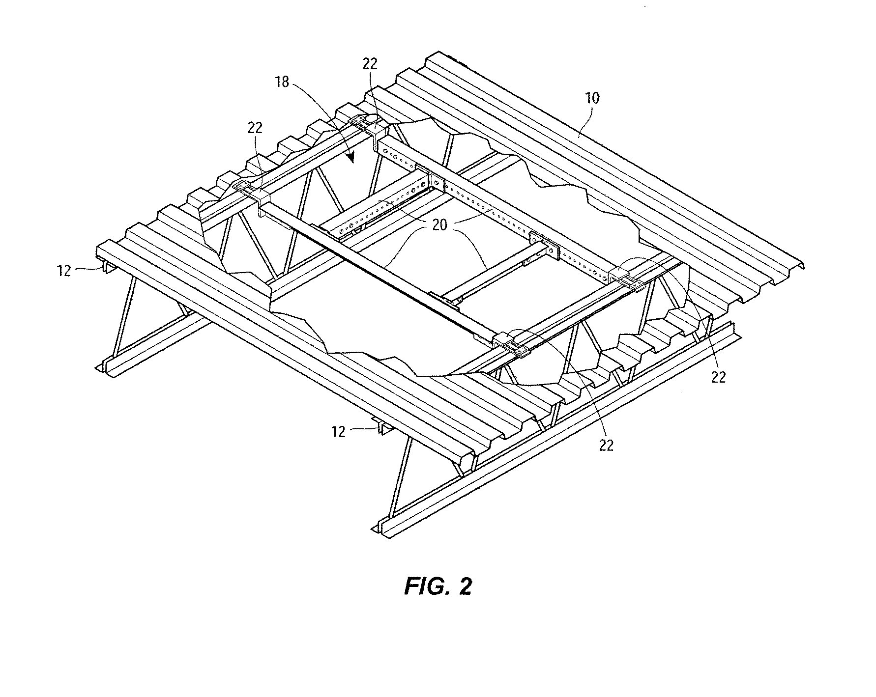
[0026]FIG. 2 shows a perspective view, partially cut away underneath the steel corrugated roof section 10. As shown in FIG. 2, a metal frame 18, typically comprised of steel framing angle 20, may be used to span the distance between two bar joists 12 and a clamp 22 is attached to the framing angle 20 at each end. Each clamp 22 is then attached to a respective bar joist 12. Other pieces of framing angle 20 are then used to...


PUM


Abstract

A clamp for use with metal bar joists (or beams) has one or more steel angled bracket members or plates, adapted to fit under the corrugations of a corrugated steel roof. Each plate of the clamp is adapted to sit horizontally across a top of the bar joist perpendicular to the joist, and extend slightly over an edge of the joist. Each plate contains an elongate slot allowing a bolt to be inserted through the slot. A retainer heel clip is secured to an end of each such bolt. This retainer heel clip is tightened to the underside of the top flange of the bar joist using a washer and a threaded plate or nut, thus providing a clamping action. Each clamp has a vertical attachment tongue section of steel welded to it, including one or more elongate slots which complement perforations that occur along the length of a steel framing angle, allowing bolts to attach the clamp and the framing angle together. A pair of the clamps may be used to secure a pair of support angles for supporting a rod for hanging objects at desired locations within a roof support structure.

Description

FIELD OF THE DISCLOSURE[0001]This disclosure relates to a clamp for use with metal bar joists and beams in order to secure cross members to the bar joists.BACKGROUND OF THE DISCLOSURE[0002]In building construction, and in steel-framed building construction in particular, metal bar joists are used as roof framing, typically under corrugated roof decking. The metal bar joists are also used to hang such items as lighting fixtures, sprinkler header assemblies, product conveyors, HVAC equipment, drywall for ceilings, and the like. For large equipment components, such as some air conditioning units, it is necessary to cut through sections of the corrugated roof decking to form an opening sized to receive the large equipment. Openings are also formed by cutting through sections of roof decking for other purposes, such as to create roof access openings.[0003]In order to reinforce the weakened roof decking above the bar joist structure once such openings are formed, the typical practice is t...

Claims


Application Information

Patent Timeline
IPC IPC(8): E04C2/32
CPCE04C2003/026Y10T24/44026E04D13/031
Inventor MOREY, DOUGLAS H.
Owner MOREY DOUGLAS H
Why Eureka
Try Eureka