Eureka AIR delivers breakthrough ideas for toughest innovation challenges, trusted by R&D personnel around the world.

Ground freezing method and apparatus with geothermal gradient compensation

a geothermal gradient and ground freezing technology, applied in the field of artificial ground freezing, can solve the problems of uneven subterranean frozen barrier formation, lack of uniform ground freezing from top to bottom, long time, etc., and achieve the effect of improving functionality

Inactive Publication Date: 2007-11-22
LAYNE CHRISTENSEN COMPANY
View PDF9 Cites 14 Cited by
  • Summary
  • Abstract
  • Description
  • Claims
  • Application Information

AI Technical Summary

Benefits of technology

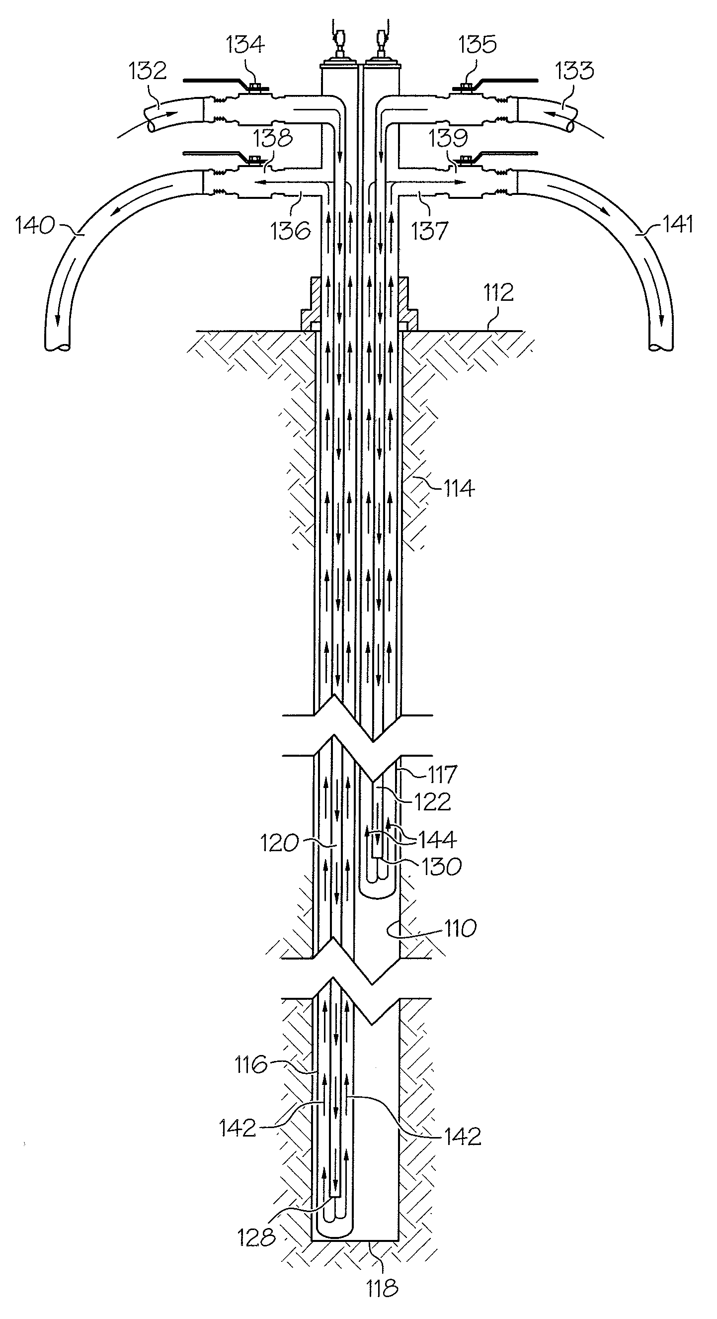
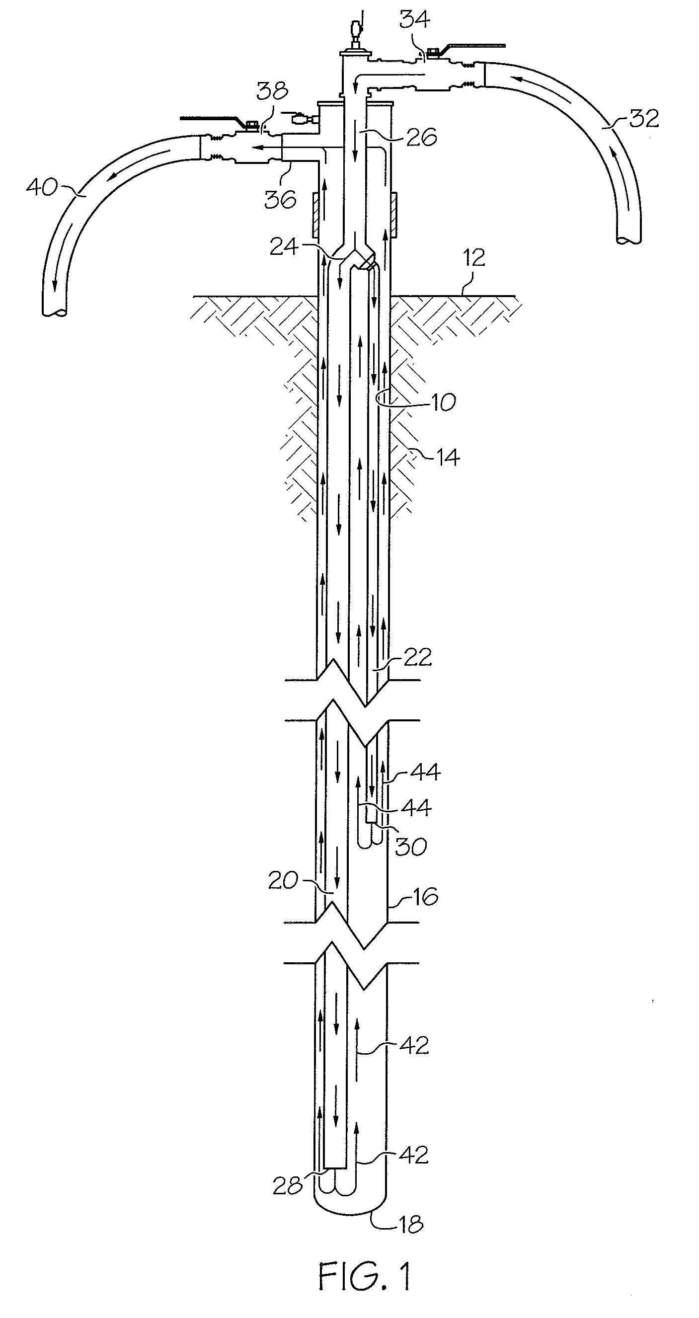
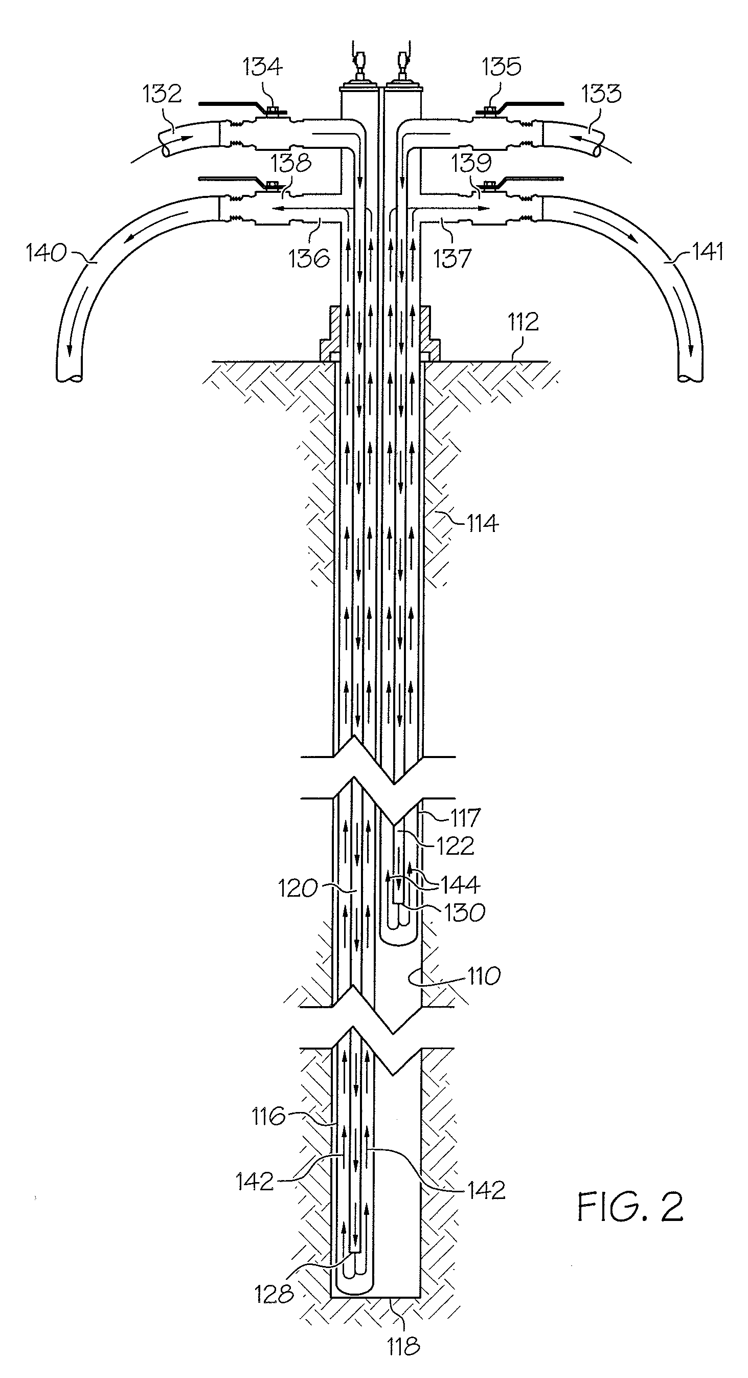
[0005]In accordance with the invention, a bore that is drilled in the ground can be equipped with one or more freeze pipes. In the case of a bore with a single freeze pipe, at least two separate feed pipes are provided extending to different depths. The longer feed pipe is larger in diameter so that more refrigerant is supplied to the bottom area of the well where the earth is warmer due to geothermal gradients. By properly sizing the pipes based on the bore size and depth, the earth around the freeze pipe can be frozen in a relatively uniform manner from bottom to top. The refrigerant from the freeze pipe can be collected and recirculated through other bores. The freeze pipes and feed pipes can be of uniform diameter, or they can be dual diameter pipes with transition areas at a depth near the end of the shorter feed pipe.
[0007]Using the techniques of the present invention, the frozen subterranean barrier is formed more uniformly than is achieved by a single feed pipe in a single freeze pipe, and compensation is made for geothermal gradients in a way that results in an economically formed subterranean barrier that exhibits improved functionality.

Problems solved by technology

In applications requiring the ground to be frozen to a substantial depth, geothermal gradients can lead to a lack of uniformity in the freezing of the ground from top to bottom.
Because the deeper areas are warmer due to the presence of geothermal gradients, they require a longer time to freeze, a problem that increases with increasing bore depth.
As a result, the shallower areas freeze more quickly, and the subterranean frozen barrier that is formed is uneven.
In some applications, this can be a significant problem that detracts from the ability of the barrier to function as intended.

Method used


Image

  • Ground freezing method and apparatus with geothermal gradient compensation
  • Ground freezing method and apparatus with geothermal gradient compensation
  • Ground freezing method and apparatus with geothermal gradient compensation

Examples


Embodiment Construction

[0013]Referring now to the drawings in more detail and initially to FIG. 1, the present invention is directed to a method and apparatus for ground freezing which involves drilling of a bore 10 downwardly from the surface 12 into the ground or earth 14. A freeze pipe 16 which may be constructed of steel or another metal is installed in the bore 10 generally in contact with the sidewall of the bore. The freeze pipe 16 may extend to the bottom or base 18 of the bore 10.

[0014]Extending side by side within the freeze pipe 16 are a pair of feed pipes 20 and 22. At their upper ends, pipes 20 and 22 are connected by a Y fitting 24 with a common supply pipe 26. Pipe 20 is substantially longer than pipe 22 and extends downwardly from the Y fitting 24 to an open lower end 28 which is spaced slightly above the bottom of the freeze pipe 16 near the base 18 of the bore. Pipe 22 has an open lower end 30 which is located well above end 28 of pipe 20 at a mid-depth location within the freeze pipe 16...


PUM


Abstract

A ground freezing method and apparatus compensates for geothermal gradients by supplying more refrigerant to deeper parts of the earth. One or more metal freeze pipes are installed in a bore and equipped with one or more feed pipes. The feed pipes extend to different depths with the longer feed pipes being larger to supply more refrigerant to greater depths and achieve uniform top to bottom ground freezing despite the effects of geothermal gradients.

Description

FIELD OF THE INVENTION[0001]This invention relates generally to artificial ground freezing and is directed more specifically to improved ground freezing techniques that compensate for geothermal gradients.BACKGROUND OF THE INVENTION[0002]Artificial ground freezing is used to freeze selected areas of the ground for a variety of different purposes, including temporary earth support for excavations, ground water containment and control, confinement of hazardous materials in the ground, and the creation of impermeable zones for hydrocarbon or mineral extraction or processing. Typically, spaced apart bores are drilled and equipped with metal freeze pipes installed along a barrier line or around a perimeter of a proposed excavation or other site. Feed pipes extend into the freeze pipes and direct a refrigerant to the base areas of the bores. The refrigerant then flows upwardly in the freeze pipes and freezes the earth around them. The refrigerant is collected and cooled again, and then ci...

Claims


Application Information

Patent Timeline
IPC IPC(8): F25C1/00F25D23/12
CPCE02D3/115E02D19/14Y02E10/125F24J3/084E21B36/001F24T10/17Y02E10/10
Inventor SOPKO, JOSEPH A.
Owner LAYNE CHRISTENSEN COMPANY
Why Eureka
Eureka Blog
Learn More