Multi-layer wick in loop heat pipe

a loop heat pipe and multi-layer technology, applied in indirect heat exchangers, lighting and heating apparatus, etc., can solve the problems of large heat leakage, poor thermal conductivity, and large heat leakag

Active Publication Date: 2007-11-22
THE BOEING CO
View PDF10 Cites 44 Cited by
  • Summary
  • Abstract
  • Description
  • Claims
  • Application Information

AI Technical Summary

Problems solved by technology

This large temperature difference indicates a large thermal resistance from the heating surface to the liquid / vapor interface due to the poor thermal conductivity of ceramic material.
Similarly, with FIG. 4b, where groove 24 is located in wick structure 26, a large temperature difference (ΔT) resulting in a large heat leakage is caused by poor thermal conductivity of the ceramic material and the heat transfer across the dry-zone of ceramic wick.
Using a wick structure where the primary wick is made of ceramic decreases heat leakage, however, since the ceramic wick structure has a low thermal conductivity, there is a large temperature difference (ΔT) between evaporator 22 and vapor line 10.

Method used


Image

  • Multi-layer wick in loop heat pipe
  • Multi-layer wick in loop heat pipe
  • Multi-layer wick in loop heat pipe

Examples


Embodiment Construction

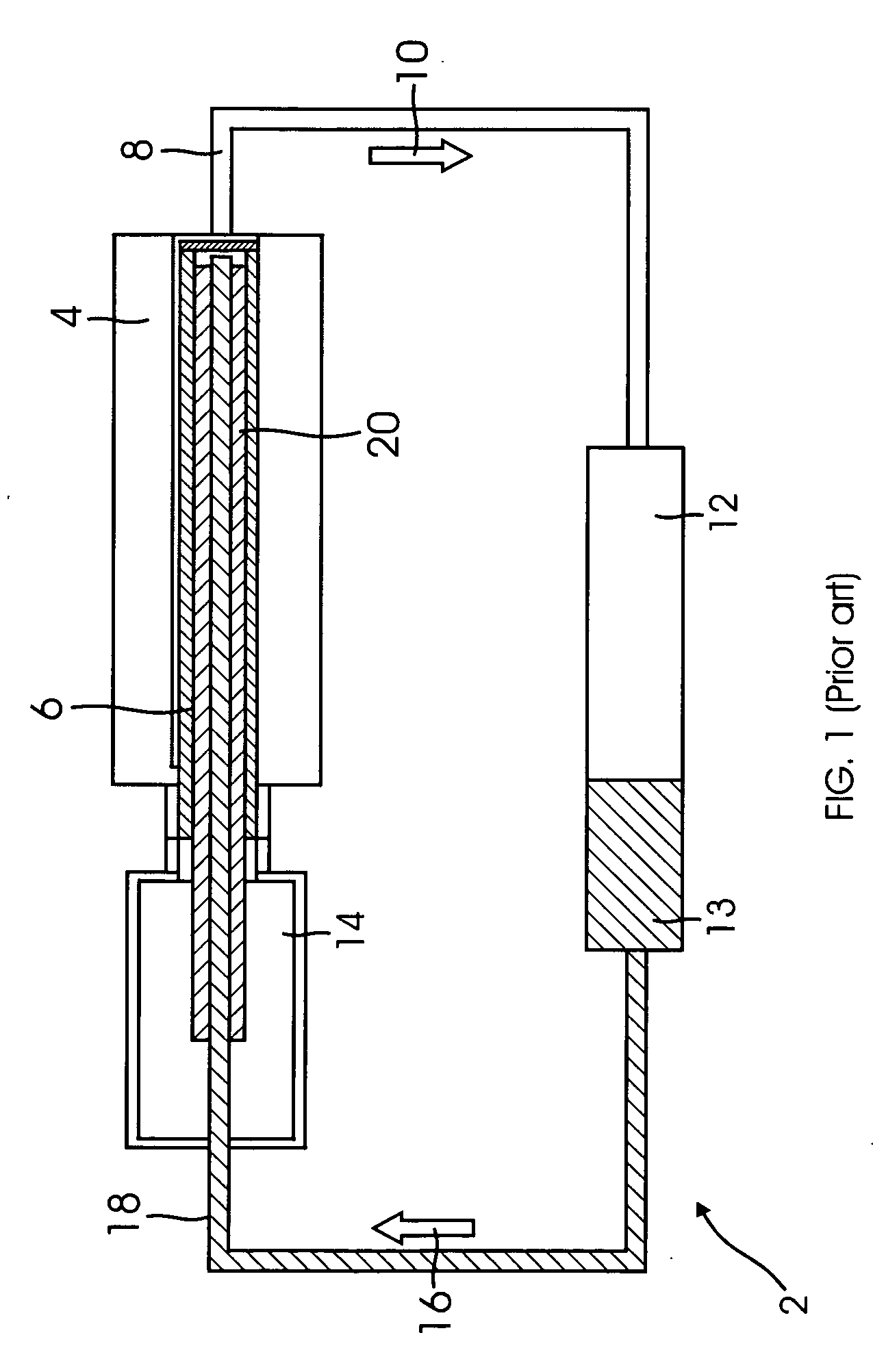
[0038]The present invention provides an improved wick structure for a loop heat pipe. The structure and performance of a loop heat pipe is described above with reference to FIG. 1. The wick structure is a multi-layer wick (i.e. has two or more layers with different materials) that prevents heat loss from the heat source to the compensation chamber of the loop heat pipe.

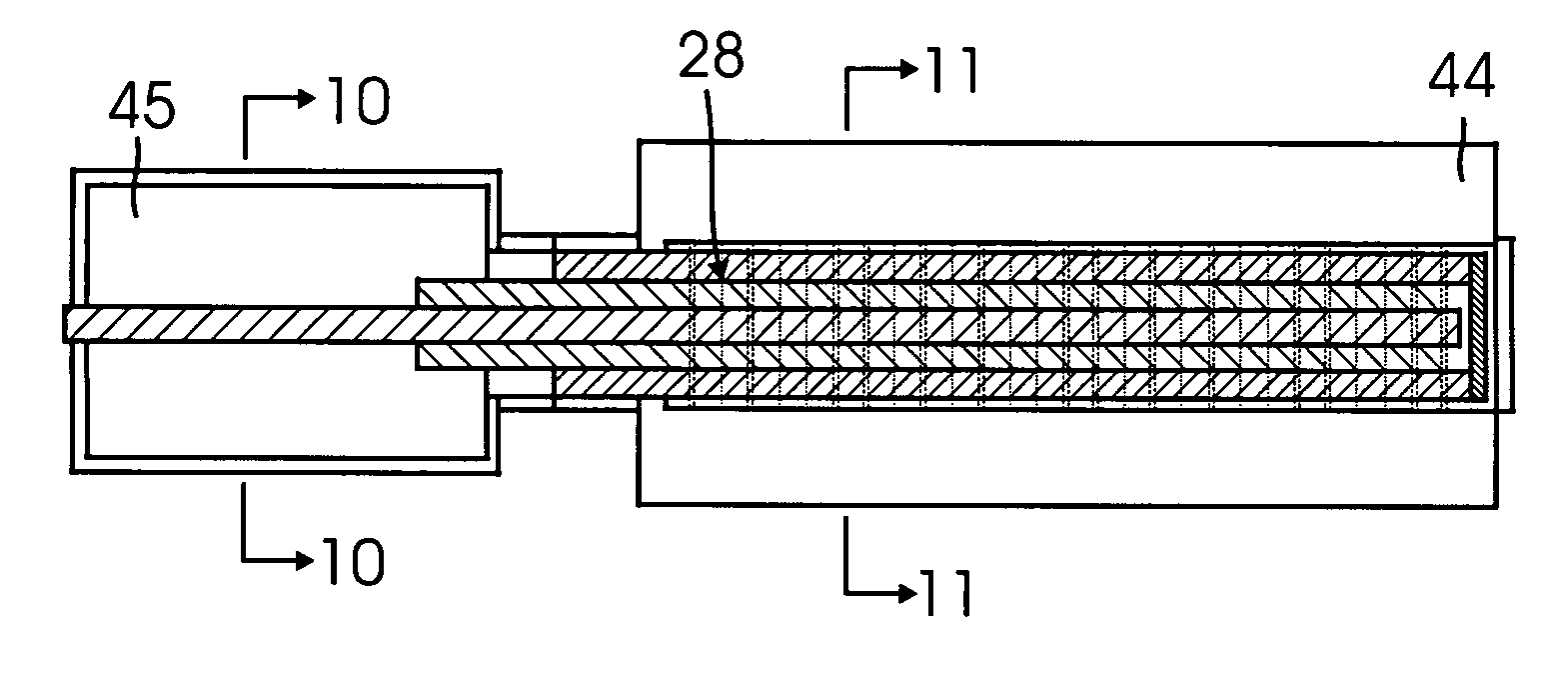
[0039]FIG. 6 illustrates a multi-layer wick 27 according to one aspect of the present invention. In the preferred embodiment, multi-layer wick 27 is comprised of a primary wick 28 having a first layer 30 and a second layer 32 surrounding a secondary wick 34. First layer 30 of primary wick 28 is made of a high thermal conductivity material such as nickel. Secondary wick 34 can be made of either low or high thermal conductivity material. Secondary wick 34 is inserted inside second layer 32 of primary wick 28 which is made of low thermal conductivity material such as ceramic and first layer 30 of the primary wick 28 surr...


PUM

PropertyMeasurementUnit
thicknessaaaaaaaaaa
porosityaaaaaaaaaa
pore sizeaaaaaaaaaa

Abstract

In one aspect of the present invention, a multi-layer wick for a loop heat pipe is provided. The multi-layer wick includes a primary wick, the primary wick comprising: a first layer; and a second layer, wherein the first layer surrounds the second layer; and a secondary wick, wherein the second layer of the primary wick surrounds the secondary wick.In another aspect of the present invention, a method of fabricating a multi-layer wick is provided. The method includes machining the outer diameter of an inner layer larger than the inner diameter of an outer layer; heating the outer layer to enlarge the inner diameter; inserting the inner layer into the outer layer; and cooling the inner layer and the outer layer.

Description

CROSS REFERENCE TO RELATED APPLICATIONS[0001]NONEBACKGROUND[0002]1. Field of Invention[0003]This invention relates generally to heat transfer devices, and more particularly, to a multi-layer wick for a loop heat pipe.[0004]2. Background of the Invention[0005]Loop beat pipes are two-phase heat transfer devices that utilize the evaporation and condensation of a working fluid to transfer heat, and the capillary forces developed in fine porous wicks to circulate the fluid. Loop heat pipes are high efficient heat transfer devices that are used in space applications to transfer heat from one source to another using a fluid in a closed system. Loop heat pipes are different from conventional heat pipes, in that a wick structure is only required in the evaporator section. The wick structure, made of fine porous material, is typically comprised of a primary wick and a secondary wick that provide the driving force for circulating the operating liquid / vapor in the loop heat pipe.[0006]FIG. 1 il...

Claims


Application Information

Patent Timeline
Patent Type & Authority Applications(United States)
IPC IPC(8): F28D15/00
CPCB23P2700/09Y10T29/49353F28D15/046F28D15/043
Inventor ASFIA, JULIE FATEMEHCAI, QINGJUNCHEN, CHUNG-LUNG
Owner THE BOEING CO
Why Eureka
Try Eureka