Minature zoom lens

a zoom lens and miniature technology, applied in the field of optical zoom lenses, can solve the problems of limiting the improvement of mechanical zoom lenses, complicated conventional photographic technologies, etc., and achieve the effects of reducing power consumption, simple structure, and compact volum

Inactive Publication Date: 2007-11-22
POWERGATE OPTICAL INC
View PDF4 Cites 25 Cited by
  • Summary
  • Abstract
  • Description
  • Claims
  • Application Information

AI Technical Summary

Benefits of technology

[0007]A primary object of the present invention is to provide a miniature zoom lens, which is provided with a more compact volume, a simpler structure, and lower power consumption.
[0008]A secondary object of the present invention is to provide a miniature zoom lens, which is provided with a front housing and a rear housing to commonly form a receiving space with an inner peripheral surface to mount at least one driving coil while a guiding module is provided with at least one guiding rod to position at least one lens assembly and a connecting plate in the front and rear housings, in operation, the driving coil being powered to generate an electromagnetic force interacting with a plurality of permanent magnets formed on at least one supporting base of the lens assembly to actuate the lens assembly to linearly move relative to the guiding rod which guides the lens assembly so that the miniature zoom lens of the present invention can be constructed without any conventional stepping motor to decrease the component amount and the entire volume thereof, and to simplify the structure thereof.
[0009]A third object of the present invention is to provide a miniature zoom lens, which generates an attractive force between the permanent magnets assembled on the supporting base and at least one positioning member assembled on the front housing, the rear housing, and the connecting plate when the driving coil is not powered so that the lens assembly is stably positioned in a predetermined position for the purpose of reducing the power consumption thereof.
[0010]A fourth object of the present invention is to provide a miniature zoom lens, which one of the lens assemblies is selected from an automatic focus mechanism to considerably shift and zoom between the lens assemblies while the automatic focus mechanism thereof is used to precisely adjust the focus thereof for the purpose of increasing the image resolution of the miniature zoom lens.
[0011]To achieve the above and other objects, the miniature zoom lens according to a preferred embodiment of the present invention comprises a front housing, a rear housing communicated with the front housing to form a receiving space, a connecting plate for connecting the front housing with the rear housing, a guiding module provided with a plurality of positioning members, at least one driving coil, and at least one guiding rod, and a lens module provided with at least one lens assembly. The guiding rod passes through the lens assembly to position the lens assembly with each other in the receiving space. The lens assembly has at least one supporting base formed with at least one lens connecting portion, and at least one lens unit screw-connected to the lens connecting portion. The supporting base has an outer peripheral surface formed with a plurality of permanent magnets while the receiving space of the front and rear housings has an inner peripheral surface mounted with a first coil and a second coil of the driving coil corresponding to the permanent magnets. The first and second coils of the driving coil are spaced apart from the permanent magnets of the supporting base in a predetermined interval. The driving coil is powered to generate an electromagnetic force interacting with the permanent magnets to actuate the lens assembly to linearly move to a predetermined position of the position members along the guiding rod. The position members are selected from yoke iron for magnetically attracting the permanent magnets when the driving coil is not powered so that the lens assembly is stably positioned in the predetermined position of the position members for the purpose of adjusting the relative positions and reducing the power consumption of the miniature zoom lens.
[0012]In another preferred embodiment of the present invention, one of the lens assemblies is selected from an automatic focus mechanism having a driving coil to actuate a lens connecting portion connecting with a lens unit to precisely adjust the focus of the lens unit for the purpose of increasing the image resolution of the miniature zoom lens.

Problems solved by technology

In early stages, conventional photographic technologies were very complicated, and only provided manual functions for manually metering, zooming, and film-winding so as to create problems in imprecision.
However, a mechanical zoom lens actuated by a stepping motor has a larger volume which can not be further reduced to become a more compact volume so as to cause a limit to improve the mechanical zoom lens.

Method used


Image

  • Minature zoom lens
  • Minature zoom lens
  • Minature zoom lens

Examples


Embodiment Construction

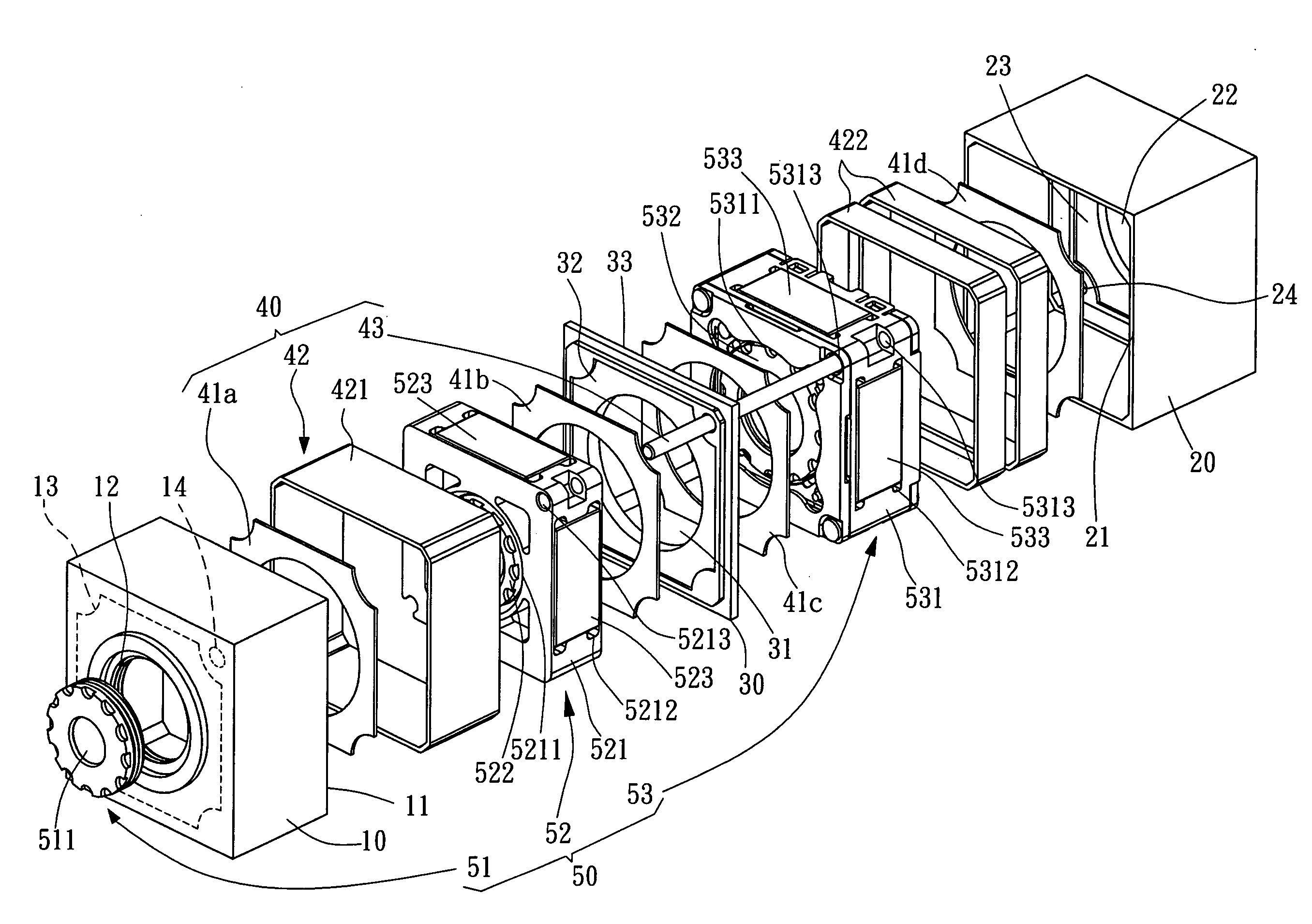
[0021]A miniature zoom lens according to a preferred embodiment of the present invention is operated by an electromagnetic force which is provided with an electromagnetic attractive force or an electromagnetic repulsive force interacting between at least one driving coil and at least one permanent magnet for shifting the permanent magnet. When the driving coil is powered by an electric current, the driving coil is excited to generate the electromagnetic attractive force attractive to a magnetic force of the permanent magnet so that the permanent magnet shifts along a guiding rod toward a predetermined direction. Contrarily, when the driving coil is powered by an electric current with a reverse direction, the driving coil is excited to generate the electromagnetic repulsive force repulsive to the magnetic force of the permanent magnet so that the permanent magnet shifts along the guiding rod toward a reverse direction. According to the electromagnetic principle as described above, th...


PUM


Abstract

A miniature zoom lens comprises a front housing, a rear housing communicated with the front housing to form a receiving space, a connecting plate for connecting the front housing with the rear housing, a guiding module provided with at least one guiding rod, and a lens module provided with at least one lens assembly. The guiding rod passes through the lens assembly to position the lens assembly with each other in the receiving space. The lens assembly has at least one supporting base formed with at least one lens connecting portion, and at least one lens unit screw-connected to the lens connecting portion. The supporting base has an outer peripheral surface formed with a plurality of permanent magnets while the receiving space of the front and rear housings has an inner peripheral surface mounted with at least one driving coil corresponding to the permanent magnets and spaced apart from each other in a predetermined interval. The driving coil is powered to generate an electromagnetic force interacting with the permanent magnets to actuate the lens assembly to linearly move relative to the guiding rod so that the lens assembly is used as a zoom mechanism for adjusting the focus of the lens unit.

Description

BACKGROUND OF INVENTION[0001]1. Field of the Invention[0002]The present invention relates to an optical zoom lens, and more particularly to a miniature zoom lens which has at least one driving coil generating an electromagnetic force interacting with at least one permanent magnet of at least one lens assembly so as to actuate the lens assembly to linearly move relative to a guiding rod for adjusting the focus of at least one lens unit on the lens assembly.[0003]2. Description of the Prior Art[0004]Referring now to FIG. 1, a mechanically actuated zoom mechanism 90 used in a conventional camera device is illustrated, which is provided with a precise driving unit 91 with high manufacturing cost (for ex., stepping motor, ultrasonic motor, piezoelectric switch, and etc.), a lens unit 92, a supporting base 93 supporting the lens unit 92 and actuated by the precise driving unit 91, and other driving elements so as to complicate the entire structure of the conventional camera device and the...

Claims


Application Information

Patent Timeline
Patent Type & Authority Applications(United States)
IPC IPC(8): G02B15/14
CPCG02B7/102
Inventor HO, WEN JENCHANG, CHI LONEYU, HENG I
Owner POWERGATE OPTICAL INC
Why Eureka
Try Eureka