LED illuminating device

a technology of led light and illuminating device, which is applied in the direction of lighting support device, lighting and heating apparatus, lighting applications, etc., can solve the problems of low power consumption, low energy efficiency, and the size of an led is very small, and achieves high versatility, energy saving, and low power consumption.

Inactive Publication Date: 2007-11-22
COLOR STARS
View PDF5 Cites 32 Cited by
  • Summary
  • Abstract
  • Description
  • Claims
  • Application Information

AI Technical Summary

Benefits of technology

[0010]One advantage of the present invention is that the proposed LED illuminating device with the rotator is highly versatile such that it is able to plug into any MR16 type socket for the retrofit of any traditional MR16 lamps and to rotate around to various angles to light up different directions, a unique design characteristic that far exceeds the possibilities of traditional illumination sources and conventional LED lamps.
[0011]Another advantage of the present invention is that the proposed LED illuminating device may vary in a wide range of shapes and sizes to accommodate different aesthetics and taste requirements while maintaining the heat management function. The cross-section of the linear housing can be configured in the shape of, for example, including but not limited to rectangle, square, circle, semicircle, curve, triangle, trapezoid or any kind of suitable shapes.
[0012]Still another advantage of the present invention over conventional light bulbs is that the proposed LED illuminating device is considerably energy saving. The presented LED illuminating device has low power consumption which needs only 1 W˜12 W, whereas conventional illumination devices typically requires higher power such as 100 W for lighting. Its built-in constant current driver within the plug structure ensures even lighting intensity of each LED in the array.
[0013]Yet another advantage of the present invention is that the proposed LED illuminating device with the fin-like structure on the top and bottom surfaces of the enclosure possesses good heat dissipation capability relative to conventional illumination devices.
[0014]A LED illuminating device with rotating capability for showcases or the like is disclosed in the present invention comprising an enclosure with a rectangular shape in front view and side covers attached to both ends of the enclosure. A substrate is attached within the enclosure and a plurality of light emitting diode (LED) is formed on and along the substrate. A transparent front cover is attached to the front side of the enclosure and a rotator is connected to the enclosure to allow the enclosure being rotated via an axis to a desired angle.
[0015]The enclosure, side cover or the substrate are made of aluminum, copper or the combination thereof. The enclosure further includes fin-like architectures formed thereon to improve the thermal dissipation capability. The fin-like architectures are configured in a strip type. The cross-section shape of the enclosure includes rectangular, square, semicircular, circular, curved, triangular or trapezoid. The material of the transparent front cover includes glass, quartz, plastic or acrylic. A socket model fit for the illuminating device includes the model named as MR16, MR11, and GU10, or any other sockets with 2 holes.

Problems solved by technology

Second, LEDs typically last about 30 times longer than incandescent lamps of similar size and brightness, and on average 4 times longer than a common fluorescent.
Moreover, while a burned out lamp can have a damaging impact on aesthetics, the gradual dimming that will occur beyond the useful life of an LED-based system will not have the dramatic negative effect and will not require immediate maintenance.
Third, LEDs are very energy efficient and typically require only 10 to 20% of the power required by incandescent lamps of similar brightness.
Furthermore, the size of an LED is very small and the light rays it produces are emitted in a very narrow beam.
The use of new materials for the substrate have allowed for improved thermal conductivity which in turn create higher power consumption and net light output.
This absorption results in an increased thermal loading of the entire LED assembly.

Method used


Image

  • LED illuminating device
  • LED illuminating device
  • LED illuminating device

Examples


Embodiment Construction

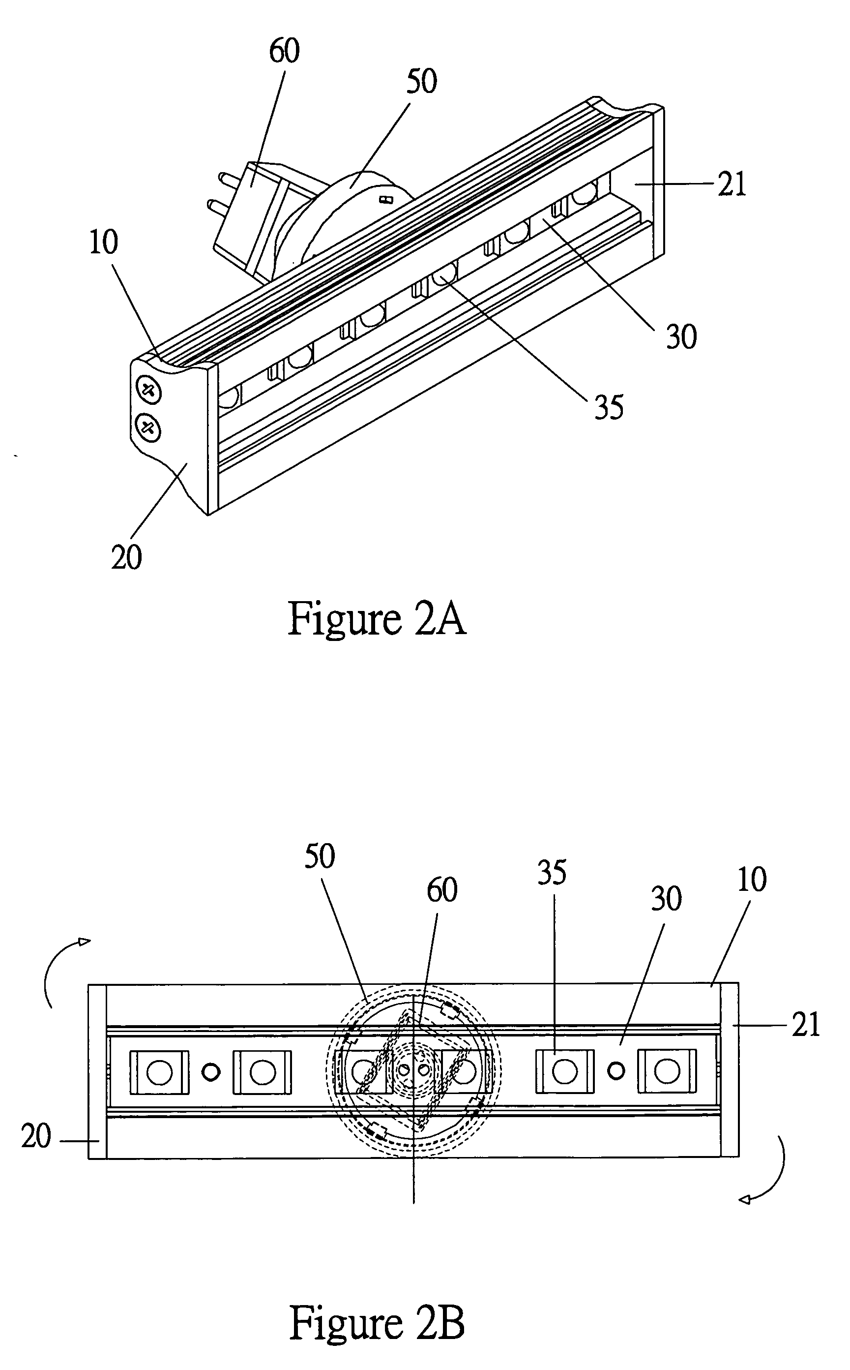
[0024]A light emitting diode (LED) illuminating device with rotating capability for showcases or the like is disclosed in the present invention. The embodiments of the invention will now be described in detailed below with reference to the accompanying drawings, and the preferred embodiment is for illustration only and not for the purpose of limiting the invention.

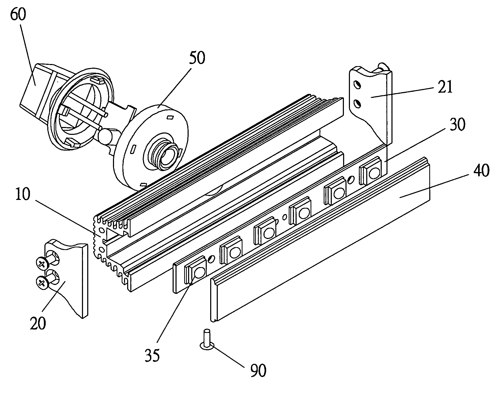
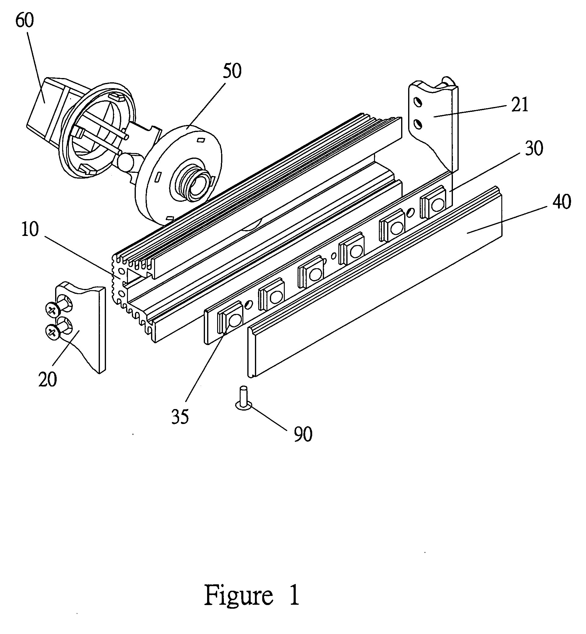
[0025]Referring to FIG. 1, there is provided a mechanical explosion drawing of the LED illuminating device according to the present invention. The LED illuminating device comprises an enclosure 10, and preferably, it is made of aluminum (Al), copper (Cu) or the combination thereof. Side covers 20 and 21 attached to both ends of the housing are employed to enclose the die. The present invention further includes a substrate 30, a transparent front cover 40 and a rotator 50. It is understood, however, the cross-section of the enclosure 10 can be in various form to suit one's particular need or for aesthetic attractiveness. To...


PUM


Abstract

A LED illuminating device with rotating capability for showcases or the like is disclosed in the present invention comprising an enclosure with a rectangular shape in front view and side covers attached to both ends of the enclosure. A substrate is attached within the enclosure and a plurality of light emitting diode (LED) is formed on and along the substrate. A transparent front cover is attached to the front side of the enclosure and a rotator is connected to the enclosure to allow the enclosure being rotated via an axis to a desired angle.

Description

FIELD OF THE INVENTION[0001]The present invention relates generally to light emitting diode (LED) illuminating devices, and more particularly to a LED illuminating device with rotating capability for showcases or the like.BACKGROUND OF THE INVENTION[0002]Light emitting diodes (LEDs) have become a significant illumination technology with a wide variety of applications in the past few decades. Since their initial invention, LEDs have been utilized in numerous diverse applications such as watches, calculators, remote controls, cell phones, indicator lights and backlights for many common gadgets and household devices. The technology is advancing at a rapid pace, and new applications continue to emerge as the LEDs brightness and efficiency increase.[0003]Compared with the traditional incandescent light bulbs or fluorescence sources, LEDs offer a huge variety of benefits. First of all, they are much more robust mechanically because LED lighting systems are inherently resistant to vibratio...

Claims


Application Information

Patent Timeline
Patent Type & Authority Applications(United States)
IPC IPC(8): F21V21/32
CPCF21W2131/405F21Y2101/02F21Y2103/003F21K9/13F21V3/04F21V15/015F21V29/89F21V21/30F21K9/58F21V29/507F21V29/75F21V29/767F21V17/12F21K9/23F21K9/65F21Y2103/10F21Y2115/10
Inventor CHEN, WEI-RURCHEN, SZU-TANGYU, CHI-FENG
Owner COLOR STARS
Why Eureka
Try Eureka