Motorized lamp axis assembly

a motorized lamp and assembly technology, applied in the field of track lighting, can solve the problems of difficult attachment of the motorized lamp axis on the output side, and inconvenient manual adjustment,

Inactive Publication Date: 2007-11-22
DEVLIN THOMAS E
View PDF4 Cites 32 Cited by
  • Summary
  • Abstract
  • Description
  • Claims
  • Application Information

AI Technical Summary

Benefits of technology

[0009]It is an object of the present invention to provide motorized adjustability to existing lamp designs with minimal modification of such designs. It...

Problems solved by technology

This sort of assembly has special mechanical requirements, and does not conveniently allow for manual adjustability.
Su...

Method used


Image

  • Motorized lamp axis assembly
  • Motorized lamp axis assembly
  • Motorized lamp axis assembly

Examples


Embodiment Construction

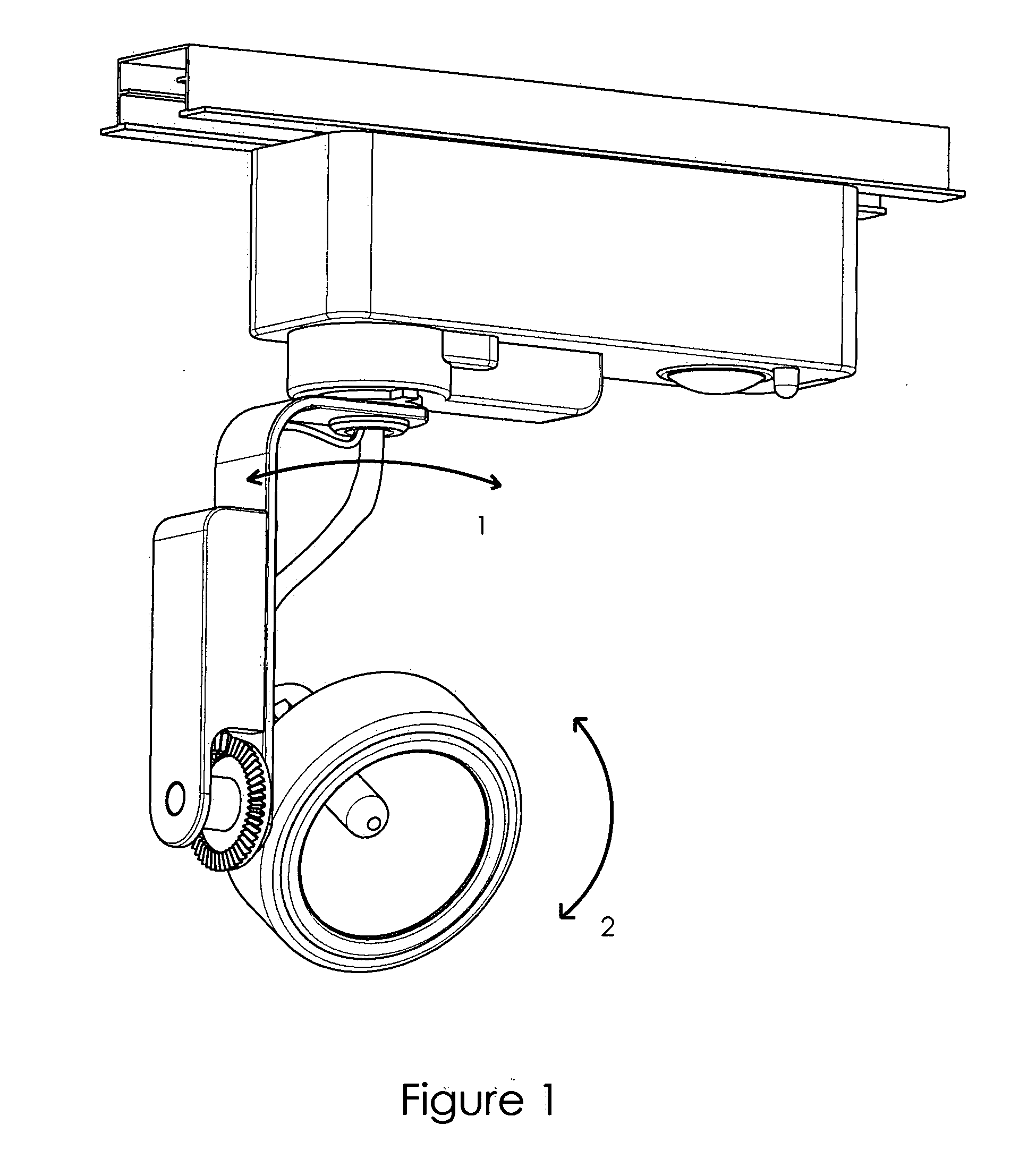
[0026]FIG. 1 depicts a typical low voltage track lighting fixture that has been modified for motorized actuation of pan axis 1 and tilt axis 2. This is a very small fixture and was chosen to illustrate how this motor system can fit virtually any lamp.

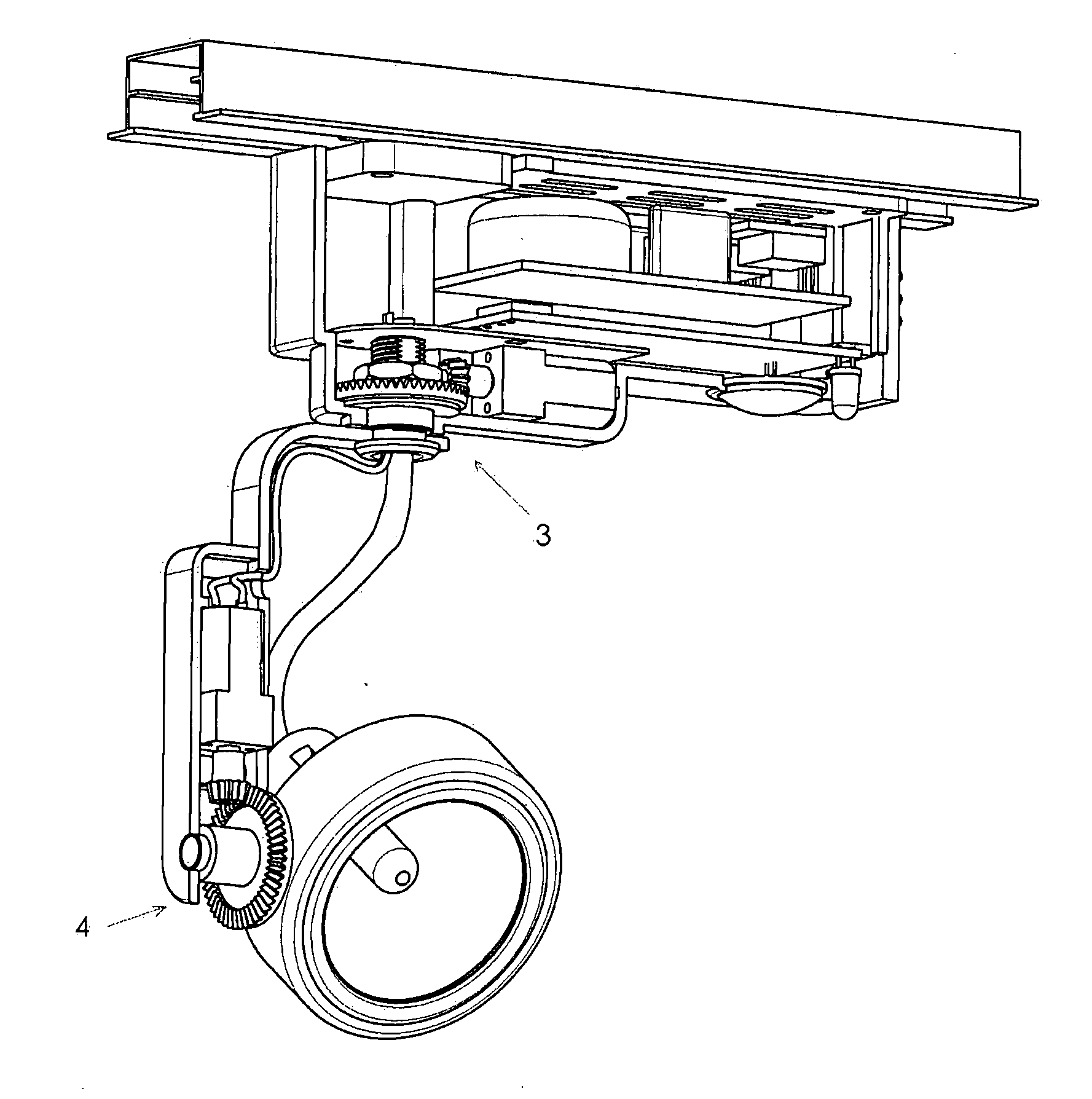
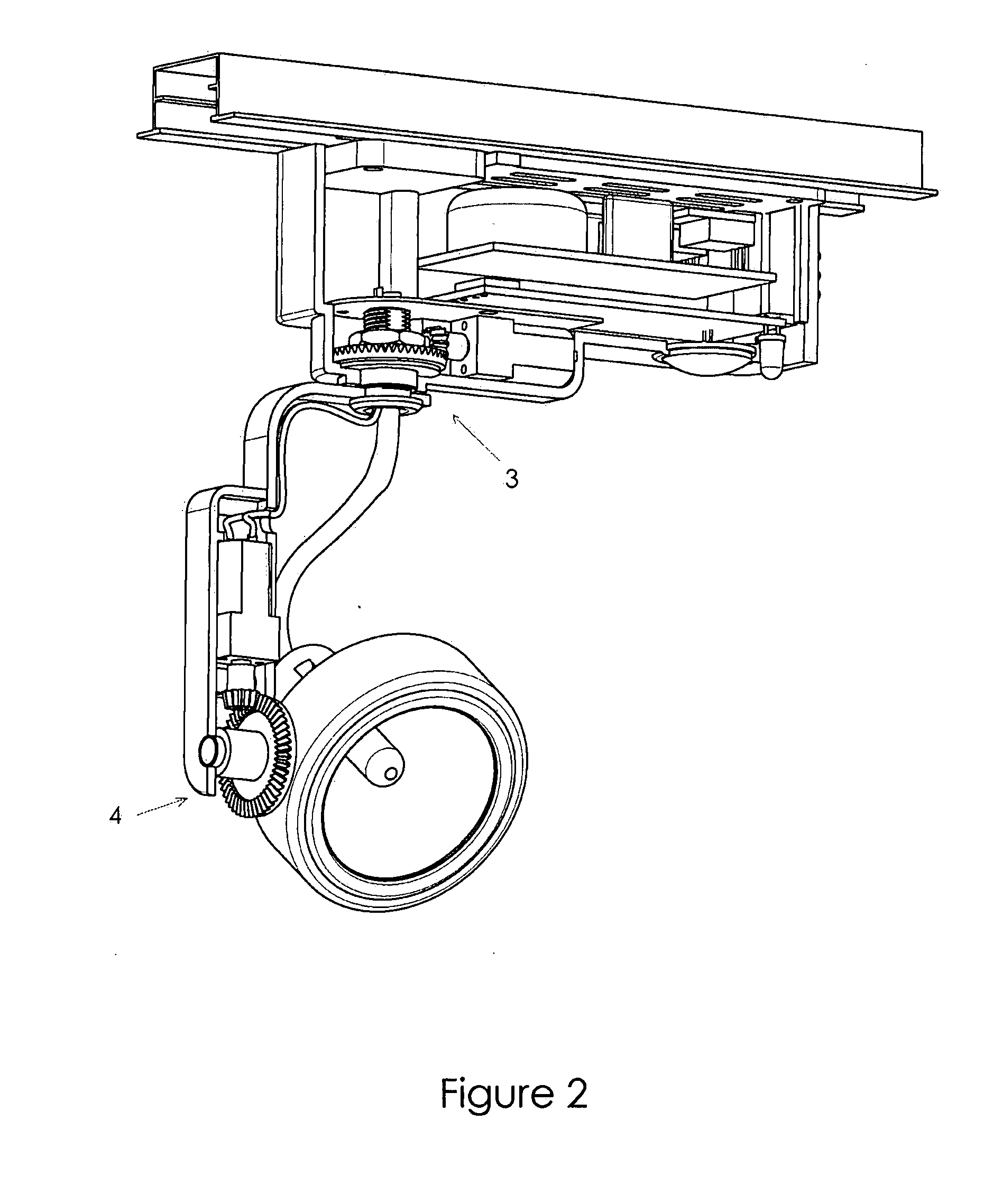
[0027]FIG. 2 is a cut-away of FIG. 1, showing pan axis motor gear assembly 3 and tilt axis motor gear assembly 4.

[0028]FIG. 3 is an exploded view of the lamp assembly shown in FIG. 1. Track mount 21 (in cooperation with latch 20) mounts housing 19 to track 10, and serves as an electrical connector to supply track power to socket 14 and low-voltage power supply and / or lamp control circuitry 11. Motor control Board 12 receives optical control signals through control window 23. Housing top 22 may be ventilated to facilitate heat exchange from power supply circuitry 11.

[0029]Motor control board 12 controls tilt motor 17 through tilt motor wiring 16. In a preferred embodiment, tilt motor 17 is a miniature gearmotor, whose output gear 18 rota...


PUM


Abstract

A method and apparatus of motorizing pan and tilt axes of existing track lighting fixture designs for minimal cost and with minimal impact on existing aesthetic design is presented. The inherently-built-in clutch of this design allows manual adjustment of lamp orientation as well as motorized adjustment, and obviates the need for expensive current limit circuitry and/or limit switches in the design. A beveled-gear embodiment provides for easy fine-tuning of the axial position of the beveled gearmotor output gears, which facilitates precise gear meshing even with large mechanical tolerance stack-up.

Description

CROSS-REFERENCE TO RELATED PATENT APPLICATIONS [0001]This patent application claims priority to provisional patent application No. 60 / 801,327, filed May 17, 2006, which is incorporated herein by reference.FIELD OF THE INVENTION [0002]The field of the invention relates to track lighting and to remote-controlled lights, and more specifically to lights which have motorized pan and tilt functions.BACKGROUND OF THE INVENTION [0003]Track-mounted lighting fixtures typically have two adjustable axes, pan and tilt. Typically such fixtures are designed such that the optical direction of the fixture lamp head may be adjusted by manually rotating the lamp head about these two axes. Such fixtures are typically designed to provide friction about the two axes of adjustment such that the coefficient of friction may be overcome by hand to orient the lamp head, and subsequent to the lamp head being oriented, the friction is sufficient to hold the lamp head as oriented indefinitely. Typically there ar...

Claims


Application Information

Patent Timeline
IPC IPC(8): F21V21/26
CPCF21V21/15F21V27/00F21V21/30
Inventor DEVLIN, THOMAS E.
Owner DEVLIN THOMAS E
Why Eureka
Try Eureka