Image forming apparatus

a technology of image forming apparatus and forming method, which is applied in the direction of electrographic process apparatus, instruments, optics, etc., can solve the problems of difficult charge of inability to charge toner to a predetermined potential, and inability to achieve the transfer performance of toner

Inactive Publication Date: 2007-11-22
RICOH KK
View PDF22 Cites 17 Cited by
  • Summary
  • Abstract
  • Description
  • Claims
  • Application Information

AI Technical Summary

Benefits of technology

[0013]In one exemplary embodiment, an image forming apparatus includes an image carrier configured to bear a toner image, an endless belt, and a bias applying roller. A front surface of the endless belt is configured to contact the image carrier to form a transfer nip. The bias applying roller is configured to apply a transfer bias to a back surface of the endless belt to transfer the toner image from the image carrier to the endless belt. The toner image is formed of a toner having an additive embedded rate of not less than 40 percent. The toner includes a mother particle including a binder resin and a colorant, and an external additive. The bias applying roller is located so as to satisfy the following relationship
[0014]In another exemplary embodiment, an image forming method includes applying a transfer bias with a bias applying roller to a back surface of an endless belt to transfer a toner image from an image carrier to the endless belt. A front surface of the endless belt contacts a surface of the image carrier to form a transfer nip. The image forming method also includes forming a toner having an additive embedded rate of not less than 40 percent. The toner includes a mother particle including a binder resin and a colorant, and an external additive. The image forming method also includes locating the bias applying roller so as to satisfy the following relationship
[0015]In another exemplary embodiment, a computer readable storage medium includes computer executable instructions, wherein the instructions, when executed by a processor, cause the processor to perform an image forming method. The image forming method includes applying a transfer bias with a bias applying roller to a back surface of an endless belt to transfer a toner image from an image carrier to the endless belt. A front surface of the endless belt contacts a surface of the image carrier to form a transfer nip. The image forming method also includes forming a toner having an additive embedded rate of not less than 40 percent. The toner image includes a mother particle including a binder resin and a colorant, and an external additive. The image forming method also includes locating the bias applying roller so as to satisfy the following relationship

Problems solved by technology

However, the additive may be embedded due to mechanical stress, for example when the toner is agitated in a developing unit.
When the fluidity is decreased, it is difficult to charge the toner to a predetermined potential by agitating the toner in the developing unit.
It may become difficult to electrostatically transfer the toner to the intermediate transfer belt and transfer performance of the toner is decreased.
If such reverse transfer occurs, the toner in a resulting image is partly insufficient.

Method used


Image

  • Image forming apparatus
  • Image forming apparatus
  • Image forming apparatus

Examples


Embodiment Construction

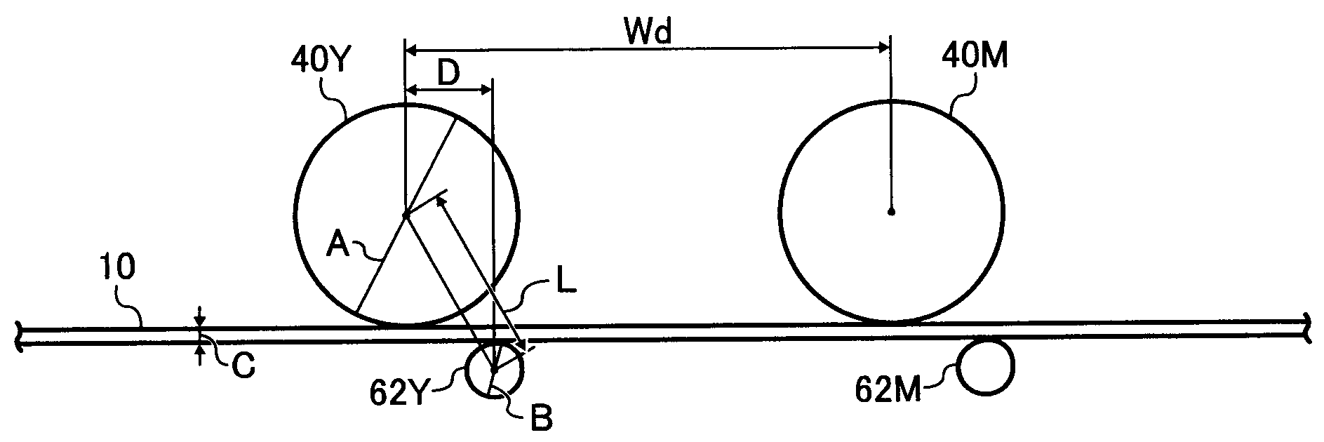
[0030]The exemplary embodiments describe an image forming apparatus that will provide better transfer performance when a toner having a better fixing property at lower temperature is used.

[0031]Having generally described this invention, further understanding can be obtained by reference to the specific exemplary embodiments that are provided herein for the purpose of illustration only and are not intended to be limiting. It is to be understood that each specific element includes all technical equivalents that operate in a similar manner.

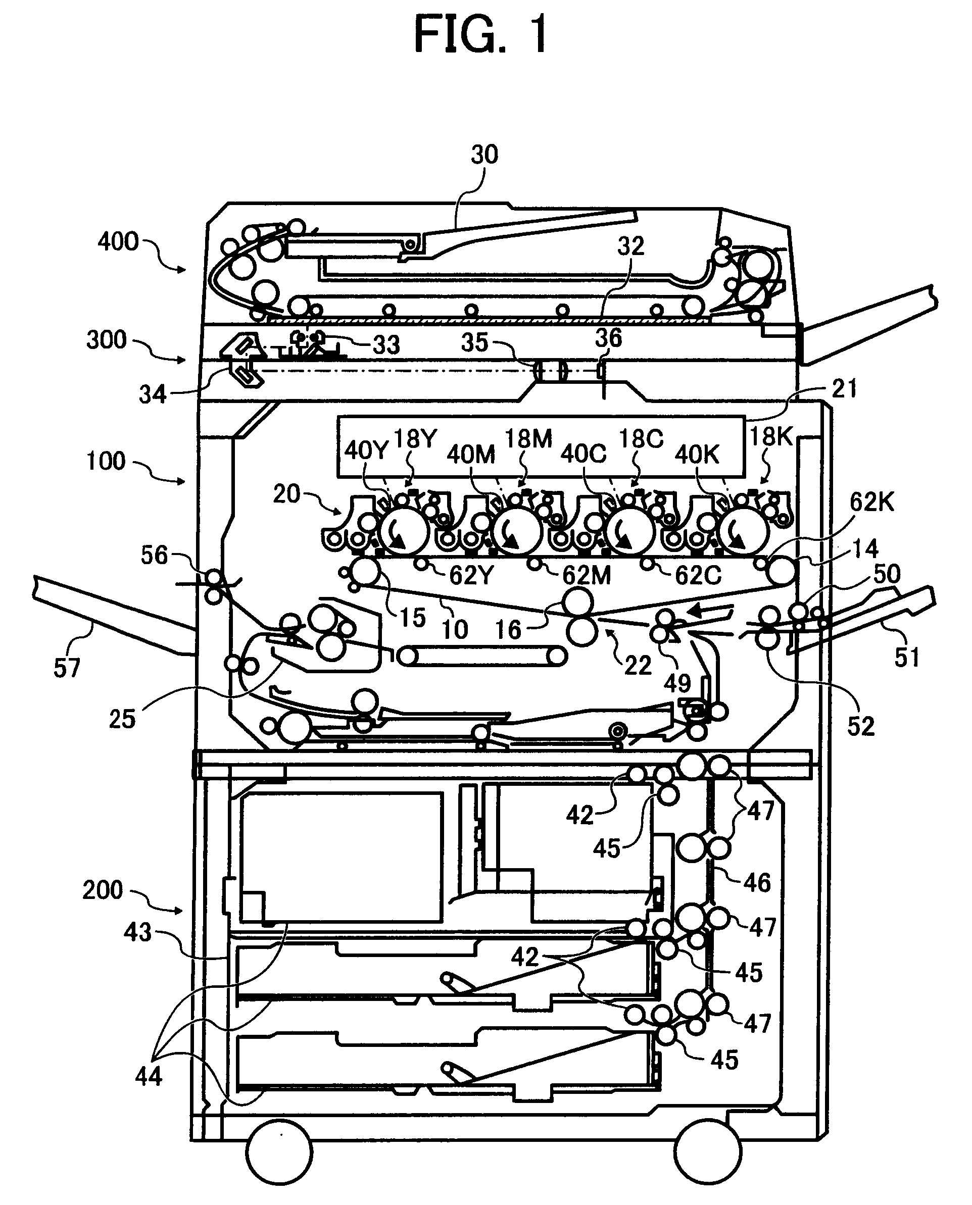
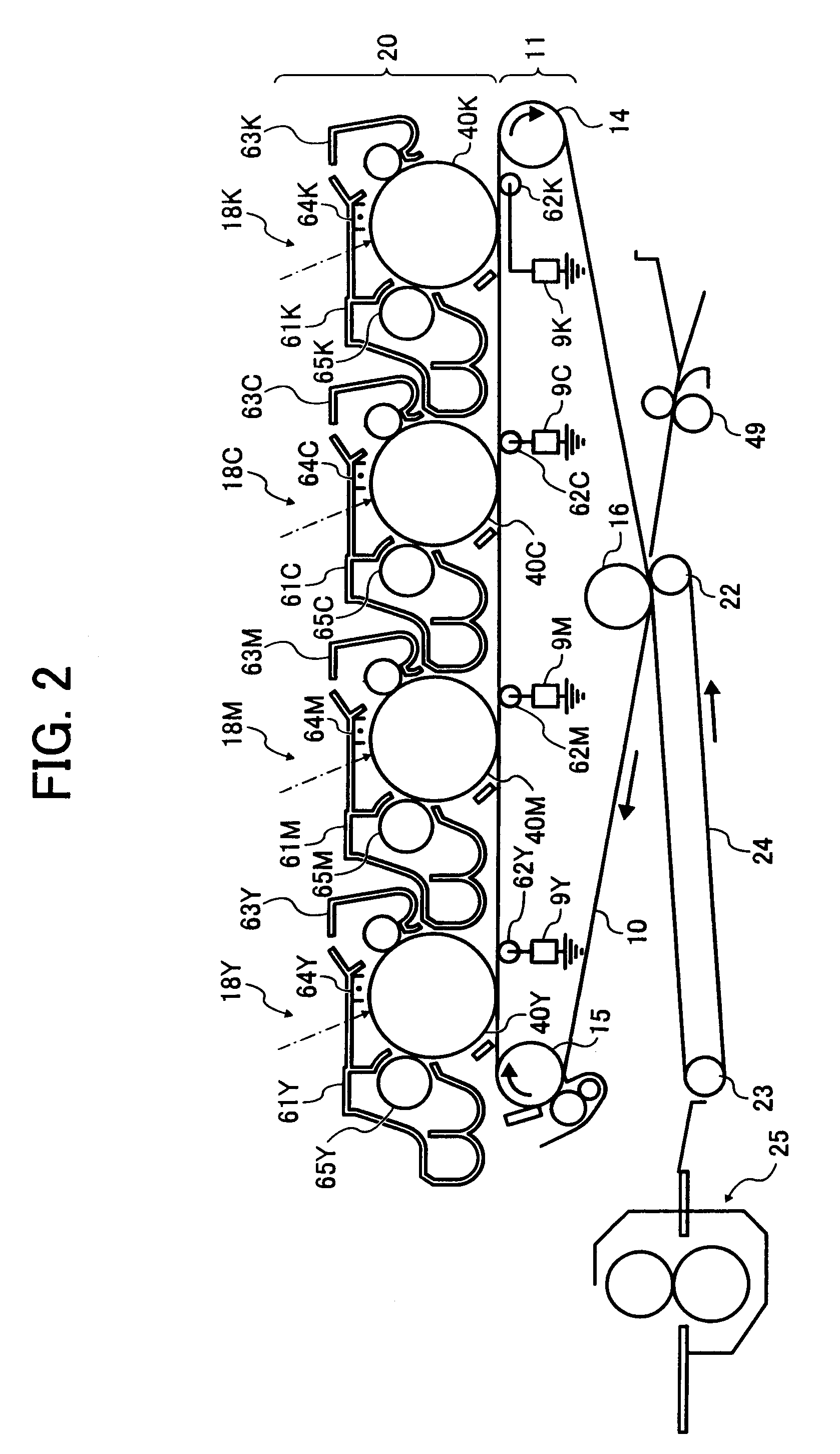
[0032]Referring now to the drawings, wherein like reference numerals designate identical or corresponding parts throughout the several views, a tandem type color image forming system according to an exemplary embodiment is described.

[0033]Referring to FIG. 1, the image forming system includes an image forming apparatus 100, a sheet feeder 200 storing sheets as transfer mediums, a scanner 300 provided over the image forming apparatus 100, and an autom...


PUM


Abstract

An image forming apparatus includes an image carrier, an endless belt whose front surface contacts the image carrier to form a transfer nip, and a bias applying roller configured to apply a transfer bias to a back surface of the endless belt. An image is formed of a toner having an additive embedded rate of not less than 40 percent and including a mother particle having a binder resin and a colorant, and an external additive. The bias applying roller is located so as to satisfy a relationship, L>(A/2)+(B/2)+C, where A is a diameter of the image carrier, B is a diameter of the bias applying roller, C is a thickness of the endless belt, and L is a distance between centers of the image carrier and the bias applying roller on a virtual plane perpendicular to an axis direction of the image carrier.

Description

BACKGROUND OF THE INVENTION[0001]1. Field of the Invention[0002]The present invention relates to an image forming apparatus and an image forming method, and more particularly to an image forming apparatus and an image forming method using an intermediate transfer method.[0003]2. Discussion of the Background[0004]An intermediate transfer method is widely used in image forming apparatuses. An example intermediate transfer image forming apparatus includes a photoreceptor, an image forming mechanism, an intermediate transfer belt, an intermediate transfer roller, and a secondary transferer. The intermediate transfer belt is an endless belt that may move in synchronization with the photoreceptor.[0005]After the surface of the photoreceptor is charged, an electrostatic latent image is formed on the photoreceptor. The electrostatic latent image is developed with a toner. The intermediate transfer roller is pressed to the photoreceptor via the intermediate transfer belt to form a transfer n...

Claims


Application Information

Patent Timeline
Patent Type & Authority Applications(United States)
IPC IPC(8): G03G15/01G03G15/16
CPCG03G15/0131G03G2215/1614G03G2215/0119G03G15/1605G03G15/162
Inventor SAWAI, YUUJINAKAYAMA, SHINYA
Owner RICOH KK
Why Eureka
Try Eureka