

Battery and Center Pin
- Summary
- Abstract
- Description
- Claims
- Application Information
AI Technical Summary
Benefits of technology
Problems solved by technology
Method used
Image

Examples
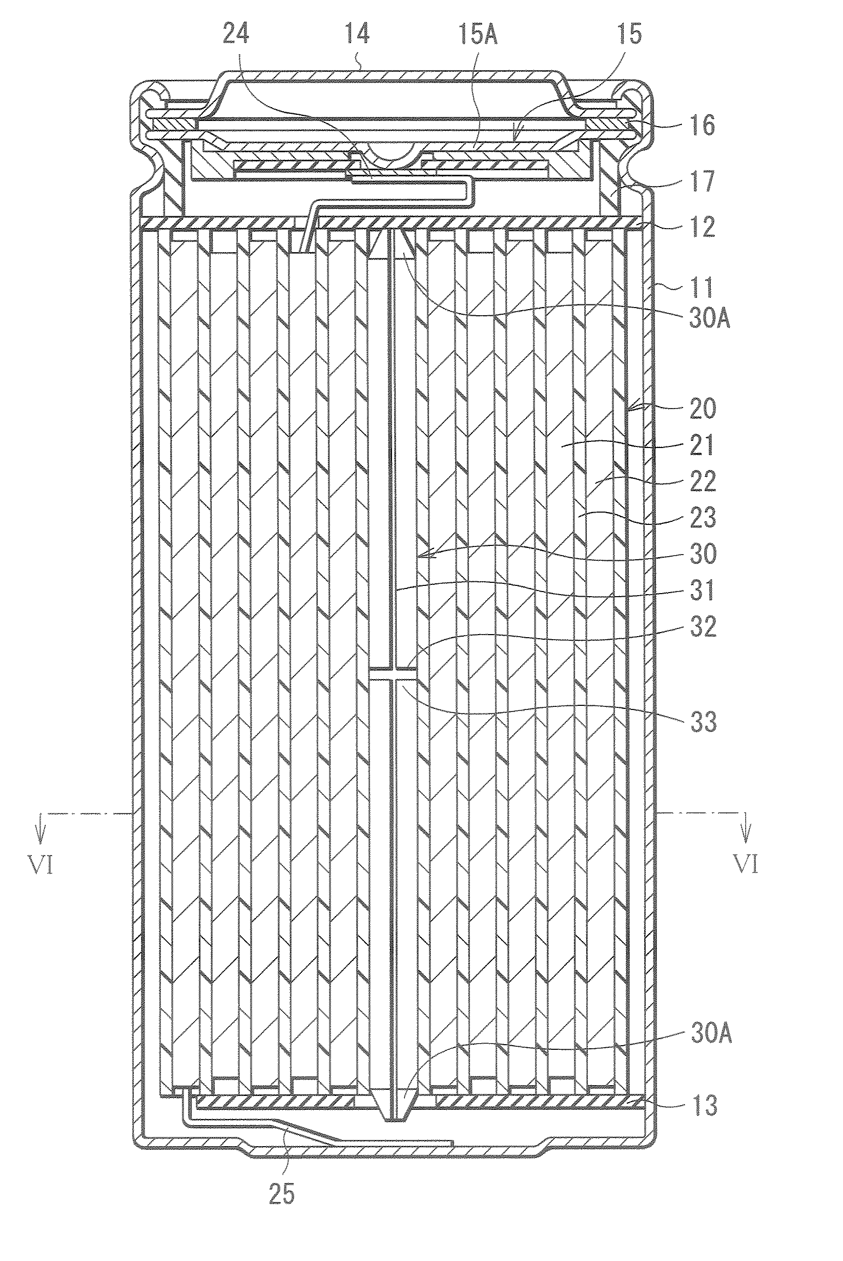
first embodiment
Modification of First Embodiment
[0098]FIG. 10 shows a modification of the foregoing center pin 30. FIG. 11 shows a structure that the center pin 30 is exploded along the cut line 31. As shown in the figures, it is possible that the first cutout 32 diagonally crosses the cut line 31 and the second cutout 34 is provided in the direction diagonally crossing the cut line 31. The second cutout 34 is not necessarily provided.
[0099]FIG. 12 shows another modification of the center pin 30. FIG. 13 shows a structure that the center pin 30 is exploded along the cut line 31. As shown in the figures, it is enough that the first cutout 32 and the second cutout 34 are shaped so that the corner 33 is projected when flattened out or broken. The shape thereof is not limited to the linear shape as that in the first embodiment, but may be V-shaped. The second cutout 34 is not necessarily provided.
[0100]FIG. 14 shows still another modification of the center pin 30. As shown in the figure, it is enough...
second embodiment
[0101]FIG. 15 shows a cross sectional structure of the center pin 30 of a secondary battery according to a second embodiment of the invention. The secondary battery has a structure, operations, and effects similar to those of the first embodiment, except that the cross sectional shape of the center pin 30 is oval and the cut line 31 is located in the long diameter of the oval. The secondary battery can be fabricated as in the first embodiment. Therefore, a description will be given in such a manner that elements identical with those of the first embodiment are affixed with the same symbol.
[0102] In the secondary battery, the cross sectional shape of the center pin 30 is oval and the cut line 31 is located in the long diameter of the oval. Therefore, for example, as shown in FIG. 16A, when the force F is applied from the direction identical with that of the long diameter of the oval, the center pin 30 is rotated inside the spirally wound electrode body 20 in the direction of the arr...
third embodiment
Modification of Third Embodiment
[0117] In this embodiment, the description has been given of the case that the cuts 35 are arranged at regular intervals. However, the cuts 35 may be arranged at irregular intervals. Further, in this embodiment, the description has been given of the case that the first portion 35A is parallel to the longitudinal direction of the center pin 30, and the second portion 35B is perpendicular to the first portion. However, as shown in FIG. 22, the first portion 35A and the second portion 35B may be arranged diagonally to the longitudinal direction of the center pin 30.
[0118] Further, in this embodiment, the description has been given of the case that the second portion 35B extends from the end of the first portion 35A perpendicular to the direction of the first portion 35A. However, as shown in FIG. 23, the second portion 35B may extend from the end of the first portion 35A at an acute angle to the first portion 35A. Further, it is possible that the second...
PUM
 Abstract
Description
Claims
Application Information