Combustion chamber of a turbomachine

Active Publication Date: 2007-11-22
SN DETUDE & DE CONSTR DE MOTEURS DAVIATION S N E C M A
View PDF9 Cites 30 Cited by
  • Summary
  • Abstract
  • Description
  • Claims
  • Application Information

AI Technical Summary

Benefits of technology

[0007]The subject of the present invention is a combustion chamber which does not have these drawbacks and which, in particula

Problems solved by technology

This solution has the drawback of being cumbersome

Method used


Image

  • Combustion chamber of a turbomachine
  • Combustion chamber of a turbomachine
  • Combustion chamber of a turbomachine

Examples


Embodiment Construction

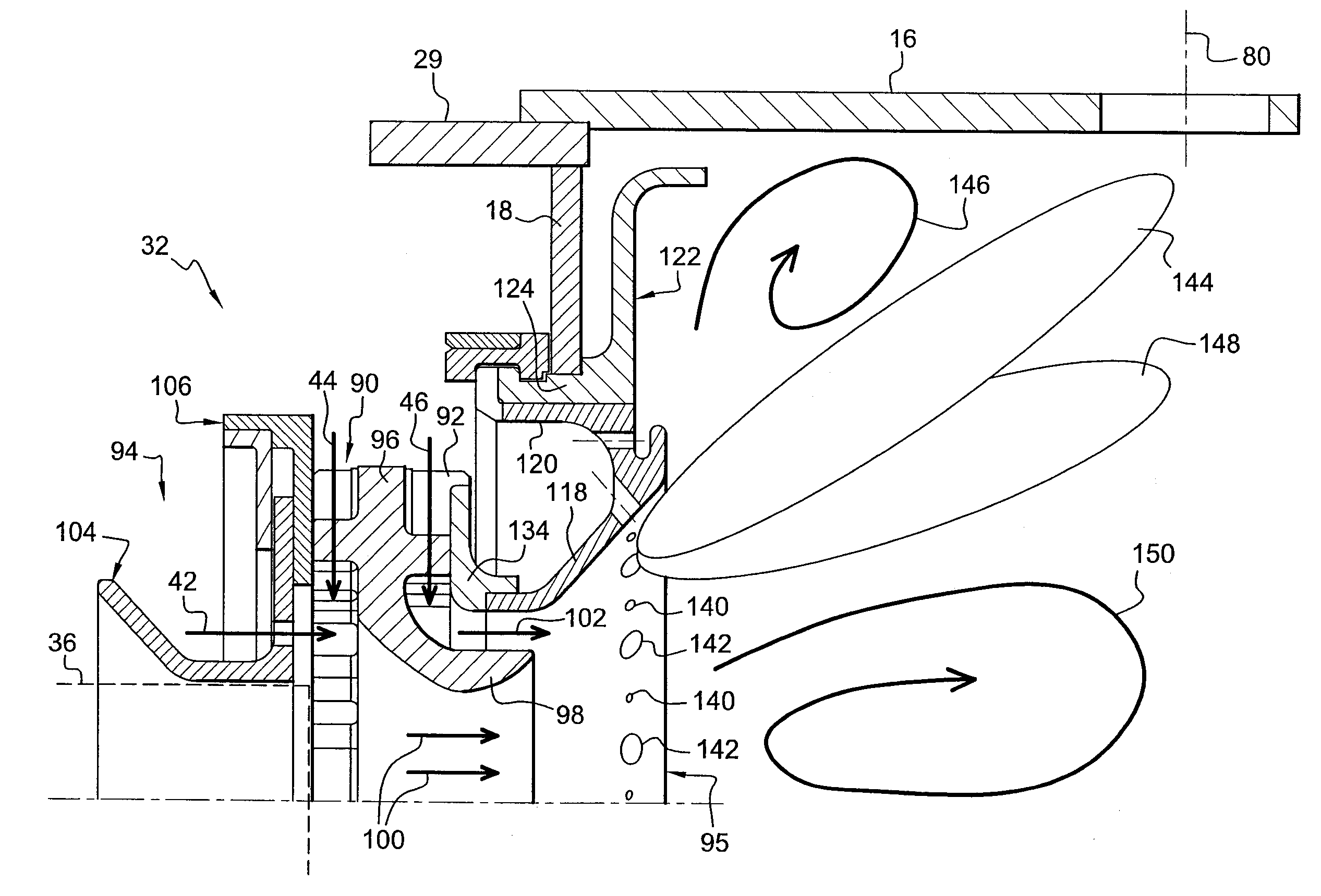
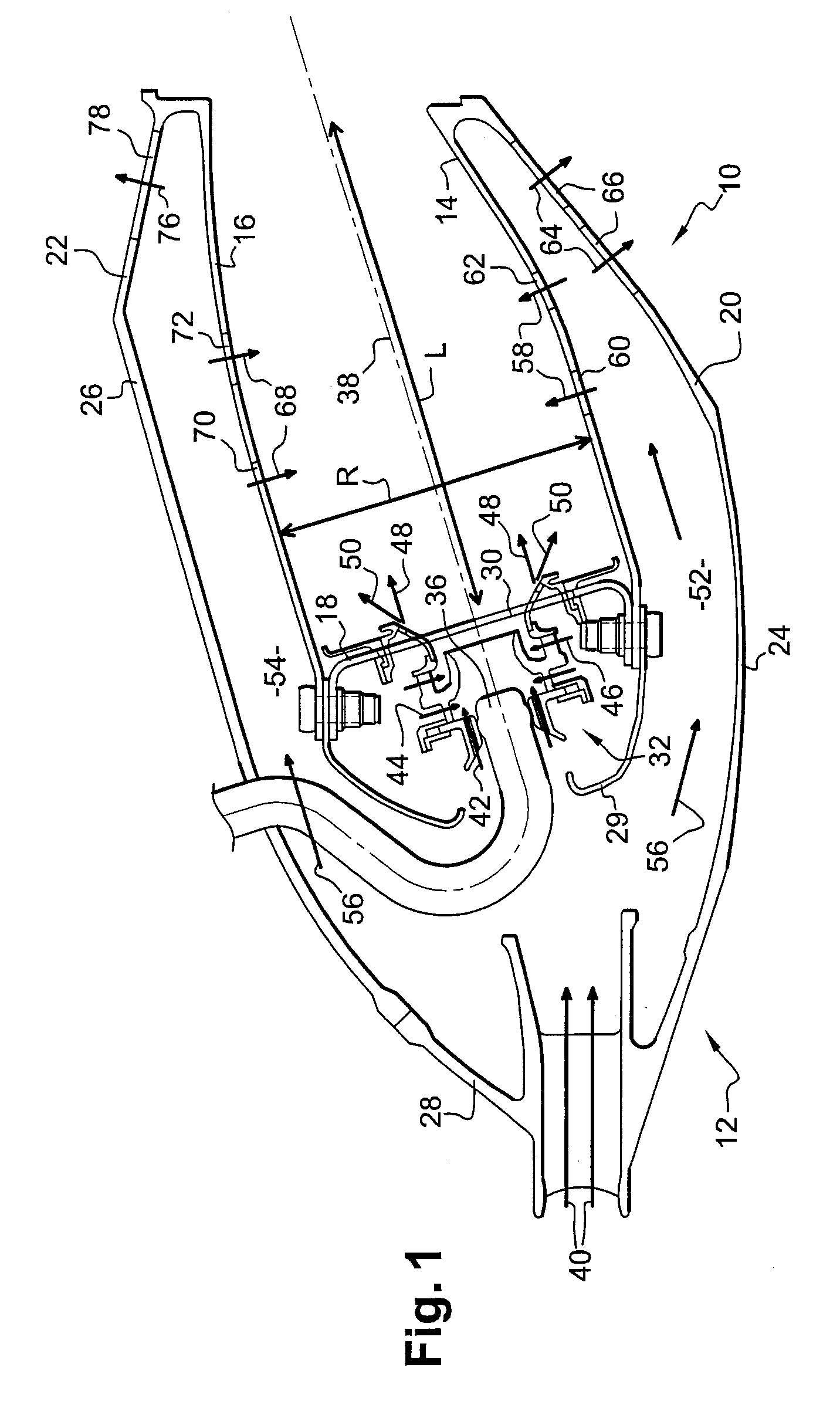
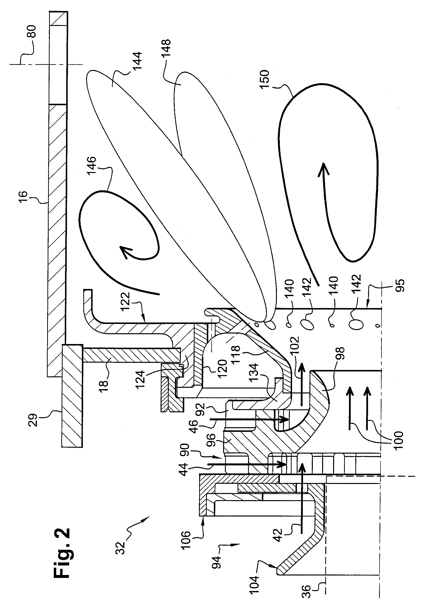
[0024]FIG. 1 represents an annular combustion chamber 10 of a turbomachine such as an aircraft turbojet, this chamber being arranged at the outlet of a diffuser 12, itself situated at the outlet of a compressor (not shown), and comprising an axisymmetric internal wall 14 and an axisymmetric external wall 16 which are connected upstream to a chamber annular endwall 18 and fastened downstream by internal 20 and external 22 frustoconical shells respectively to an internal frustoconical case 24 of the diffuser and to an external casing 26 of the chamber, the upstream end of this casing being connected to an external frustoconical case 28 of the diffuser.

[0025]An annular cowl 29 is fastened to the upstream ends of the walls 14, 16 and 18 of the chamber and comprises air flow orifices aligned with openings 30 in the chamber endwall 18, in which openings are mounted systems 32 for injecting an air / fuel mixture into the chamber, the air from the diffuser 12 and the fuel being supplied by in...


PUM


Abstract

A combustion chamber (10) of a turbomachine, comprising at least one bowl (95) with a substantially frustoconical wall that is formed with an annular row of air injection orifices, and a fuel injector (36) arranged upstream of the bowl, the annular row of air injection orifices comprising smaller-diameter orifices (140) and larger-diameter orifices (142) which are arranged in alternating fashion and with a uniform distribution around the axis of the bowl to produce two annular air/fuel mixture layers (144, 148).

Description

BACKGROUND OF THE INVENTION AND DESCRIPTION OF THE PRIOR ART[0001]The present invention relates to a combustion chamber of a turbomachine, such as an aircraft turbojet or turboprop.[0002]Combustion chambers of turbomachines must be designed to limit the production of harmful gases, such as nitrogen oxides (NOx) and carbon dioxide (CO2) which are discharged into the atmosphere.[0003]In a conventional manner, a turbomachine combustion chamber has an annular shape and comprises a plurality of mixer bowls which are mounted on the chamber endwall and uniformly distributed around the longitudinal axis of the chamber. Each bowl is mounted downstream of a fuel injector, in the axis of this injector, and comprises a substantially frustoconical wall formed with an annular row of air injection orifices to produce an annular layer of an air / fuel mixture intended to be ignited in the primary zone of the chamber.[0004]The distribution and the dimensions of the air injection orifices of the bowls ...

Claims


Application Information

Patent Timeline
IPC IPC(8): F23Q3/00F23C7/00
CPCF23R3/10Y02T50/675F23R3/286F23R3/14Y02T50/60
Inventor COMMARET, PATRICE ANDRESANDELIS, DENIS JEAN MAURICE
Owner SN DETUDE & DE CONSTR DE MOTEURS DAVIATION S N E C M A
Why Eureka
Try Eureka