Tri-state chopper for frequency conversion

a frequency conversion and tri-state technology, applied in the direction of demodulation, electrical apparatus, demodulation, etc., can solve the problems of difficult application of direct conversion to tv tuners, spurious mixing products in practical mixers,

Active Publication Date: 2007-11-22
REALTEK SEMICON CORP
View PDF5 Cites 2 Cited by
  • Summary
  • Abstract
  • Description
  • Claims
  • Application Information

AI Technical Summary

Benefits of technology

[0002]The present invention relates to tri-state chopper circuit and its application to frequency conversion, in particular to frequency conversion that suppresses harmonics mixing.

Problems solved by technology

Although the principle of direct conversion receiver has been well known in prior art, it is very difficult to apply direct conversion to a TV tuner due to a problem known as “harmonic mixing” caused by an undesired but inevitable mixing within the two mixers (130_I and 130_Q).
In particular, a practical mixer is subject to generating spurious mixing products among its input RF signal and odd-order harmonics of the LO clock.

Method used


Image

  • Tri-state chopper for frequency conversion
  • Tri-state chopper for frequency conversion
  • Tri-state chopper for frequency conversion

Examples


Embodiment Construction

[0024]The present invention relates to a tri-state chopper circuit and its application to harmonic rejection frequency conversion. While the specifications described several example embodiments of the invention considered best modes of practicing the invention, it should be understood that the invention can be implemented in many way and is not limited to the particular examples described below or to the particular manner in which any features of such examples are implemented. In other instances, well-known details are not shown or described to avoid obscuring aspects of the invention.
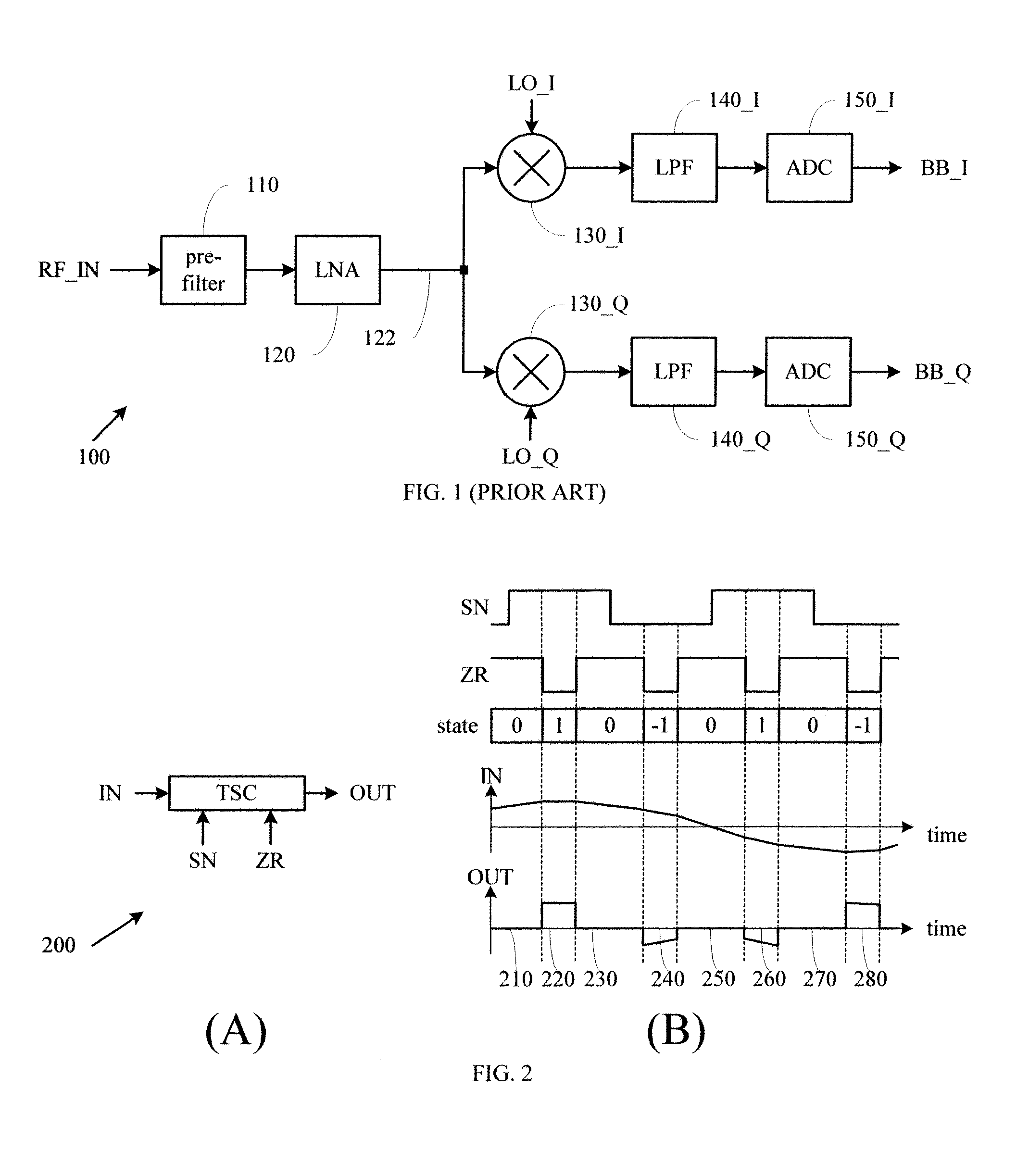
Tri-State Chopper

[0025]A tri-state chopper (TSC) receives an input signal and a ternary control signal and generates an output signal. A ternary control signal has three states, say “1,”“−1,” and “0.” In a first state (“1”), the output signal tracks the input signal in both magnitude and sign; in a second state (“−1”), the output signal tracks the input signal in magnitude but has an opposite sign; and...


PUM


Abstract

A tri-state chopper (TSC) circuit and method is disclosed. The tri-state chopper (TSC) circuit receives an input signal and a ternary signal and generates an output signal, wherein: the output signal tracks the input signal in both magnitude and sign when the ternary signal is in a first state; the output signal tracks the input signal in magnitude but has an opposite sign when the ternary signal is in a second state; and the output signal is set to zero when the ternary signal is in a third state.

Description

BACKGROUND OF THE INVENTION[0001]1. Field of the Invention[0002]The present invention relates to tri-state chopper circuit and its application to frequency conversion, in particular to frequency conversion that suppresses harmonics mixing.[0003]2. Description of Related Art[0004]Direct conversion receiver is well known in prior art. FIG. 1 depicts a functional block diagram of a typical direct conversion receiver 100, which comprises: a pre-filter 110; a LNA (low-noise amplifier) 120; an in-phase (I) path comprising a first mixer 130_I, a first LPF (low pass filter) 140_I, and a first ADC (analog-digital converter) 150_I; and a quadrature (Q) path comprising a second mixer 130_Q, a second LPF (low pass filter) 140_Q, and a second ADC (analog-digital converter) 150_Q. Pre-filter 110 performs a preliminary filtering on a RF (radio frequency) input RF_IN and passes an output to LNA 120, which performs a low-noise amplification on the output of pre-filter 110 and generates a RF signal 1...

Claims


Application Information

Patent Timeline
Patent Type & Authority Applications(United States)
IPC IPC(8): H04B1/04
CPCH03D7/165H03D3/007
Inventor LIN, CHIA-LIANG
Owner REALTEK SEMICON CORP
Why Eureka
Try Eureka