System and method for tissue specimen collection

a tissue specimen and system technology, applied in the field of tissue specimen collection, can solve the problems of ineffective separation of tissue specimen from tissue specimen retained, inability to effectively separate suction effluent that accompanies the tissue specimen from the tissue specimen retained, and large volume of potentially contaminating effluent retained in conventional traps, so as to achieve quick change and improve effluent separation

Inactive Publication Date: 2007-11-22
US ENDOSCOPY GROUP
View PDF45 Cites 43 Cited by
  • Summary
  • Abstract
  • Description
  • Claims
  • Application Information

AI Technical Summary

Benefits of technology

[0014]Thus, the various embodiments of the present invention provide many advantages that may include, but are not limited to: allowing a clinician to quickly change tissue specimen collection traps without having to immediately transfer the tissue specimen to a separate preservation fluid container; providing a self-contained, enclosed tissue specimen collection device which may be stored prior to transport to a pathology laboratory such that multiple tissue specimens collected during a single endoscopy pro

Problems solved by technology

However, conventional “sputum cup” tissue specimen traps do not provide direct co-axial fluid communication between the endoscope and the suction source (as both the inlet and outlets of the cup are defined in a “lid” or “cover” of the trap).
Thus, suction effluent that accompanies the tissue specimen may not be effectively separated from the tissue specimen retained in the basket or chamber of the trap due to the indirect suction applied to the tissue specimen.
For example, the reservoir or “cup” of such conventional traps often retains a considerable volume of potentially contaminating effluent.
Such conventional tissue specimen traps, however require a clinician to pull out the tissue specimen out of the gauze-like “filter” retained within the tube or to pull out the entire gauze-like “filter.” Such additional operations may compromise the tissue specimen thereby limiting its value as a diagnostic indicator when examined, for example, by a pathologist.
For example, removal tis

Method used


Image

  • System and method for tissue specimen collection
  • System and method for tissue specimen collection
  • System and method for tissue specimen collection

Examples


Embodiment Construction

[0029]The present inventions now will be described more fully hereinafter with reference to the accompanying drawings, in which some, but not all embodiments of the inventions are shown. Indeed, these inventions may be embodied in many different forms and should not be construed as limited to the embodiments set forth herein; rather, these embodiments are provided so that this disclosure will satisfy applicable legal requirements. Like numbers refer to like elements throughout.

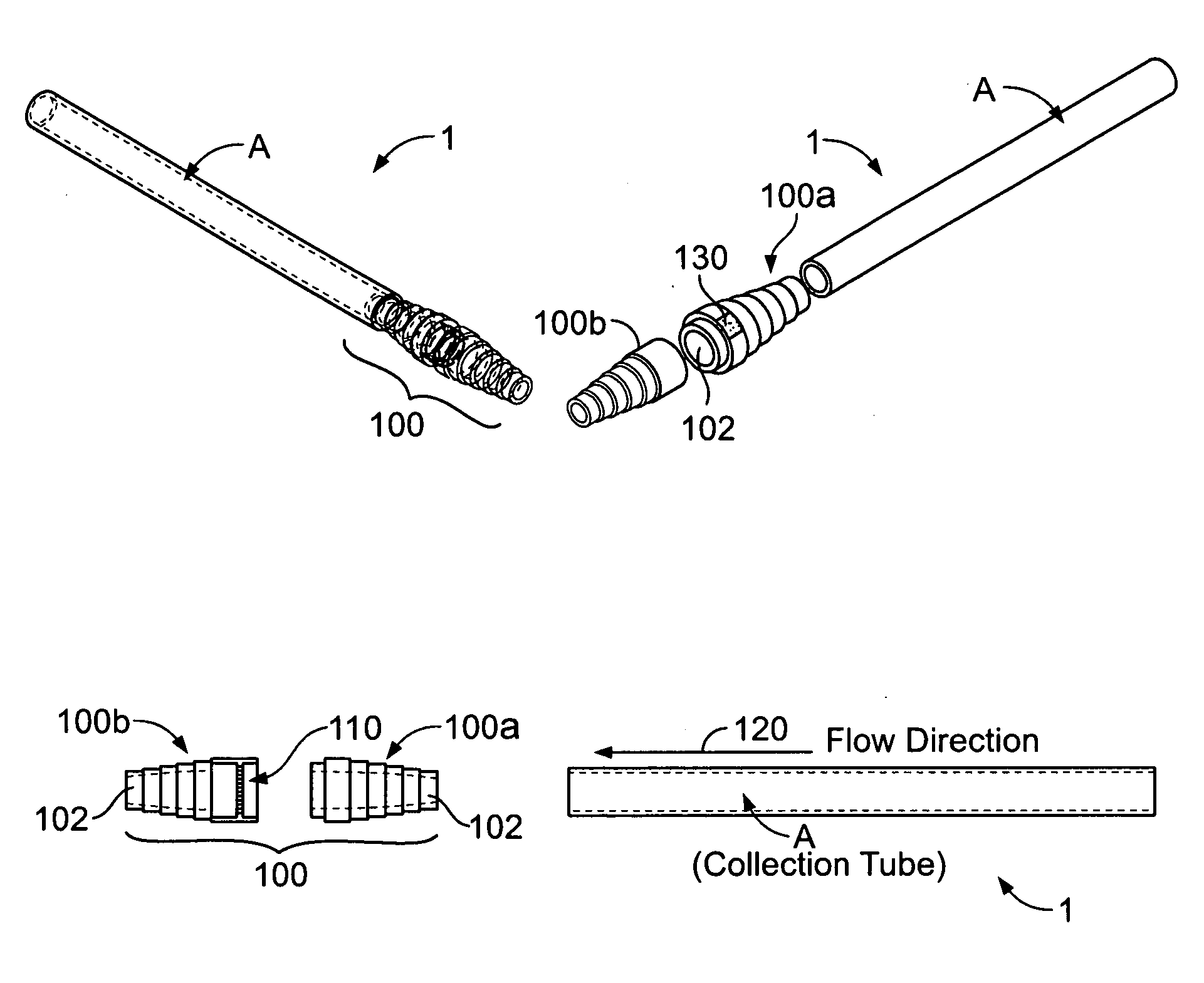
[0030]As shown generally in FIG. 1, one embodiment of the present invention provides a tissue specimen collection system 1 comprising a collection device 100 adapted to be removably and serially engaged between a suction tube B (see FIG. 4) and a collection tube A. For example, in some embodiments, the collection device 100 may be adapted to be removably and serially engaged between an endoscope collection tube A and a suction tube B such that a flow direction 120 is established through the collection device 1...


PUM


Abstract

A system and method for retaining a tissue specimen obtained via a collection tube is provided. Embodiments provide a system including a collection device removably and serially disposed between a collection tube and a suction tube so as to allow fluid communication therebetween via the collection device. The collection device includes a screen for retaining a tissue specimen drawn into the collection device by and towards the suction tube while allowing any fluid accompanying the tissue to be drawn through the collection device and into the suction tube. The system also includes one or more end caps for sealing the collection device such that the collection device may store and/or transport the retained tissue specimen in a preservation fluid. A system for identifying and organizing collection devices retaining tissue specimens from various anatomical regions is also provided.

Description

FIELD OF THE INVENTION[0001]The various embodiments of the present invention relate generally to tissue collection devices for retaining a tissue specimen drawn from a patient by a suction device during, for example, an endoscopy procedure.BACKGROUND OF THE INVENTION[0002]Endoscopic medical procedures often result in the capture of tissue specimens (such as polyps) recovered from a collection tube in communication with an endoscope during an endoscopy procedure. For example, clinicians often draw tissue specimens through an endoscope and into a collection canister via the application of suction from a suction source positioned proximal to the endoscope. Such tissue specimens are often transported to a pathology laboratory in order to generate a diagnosis based on an analysis of the tissue specimen.[0003]Various conventional tissue specimen traps have been developed for placement between the patient and the collection canister (and a corresponding suction source) in an attempt to sep...

Claims


Application Information

Patent Timeline
IPC IPC(8): A61B10/00
CPCA61B10/0096A61C17/046A61B10/0283A61B90/96A61B90/90A61B90/92A61B90/94A61B90/98A61C17/065A61B10/04A61M1/79A61M1/86A61B1/015A61M2205/0216A61M2205/125
Inventor CUSHNER, JEFFREY B.KURZYNA, PETER M.WOLCOTT, KENNETH E.
Owner US ENDOSCOPY GROUP
Why Eureka
Try Eureka