Apparatus, systems, and methods for continuous pressure technique therapy

a technology of continuous pressure and apparatus, applied in the field of apparatus, systems, and methods for continuous pressure technique therapy, can solve the problems of triggering pain and ineffective treatment for all individuals, and achieve the effect of reducing pain

Inactive Publication Date: 2007-11-22
KHORASSANI ZADEH DAVID
View PDF16 Cites 79 Cited by
  • Summary
  • Abstract
  • Description
  • Claims
  • Application Information

AI Technical Summary

Benefits of technology

[0082] Additional applications of the method, system and device of the invention also include elimination of acute and chronic pains, irregardless of the origin of the pain (for example pain after accidents and injury; pre-surgery conditions involving muscle spasm). The applications sites can be used for one or all of these areas: skin; tendons; bone-tendon-muscle junctions; muscles; nerves; ligaments; bones; joints; and fascia. The method used to induce a relief of pain in patients is based on the use of a deep continuous pressure-application, which is applied to any part of the body
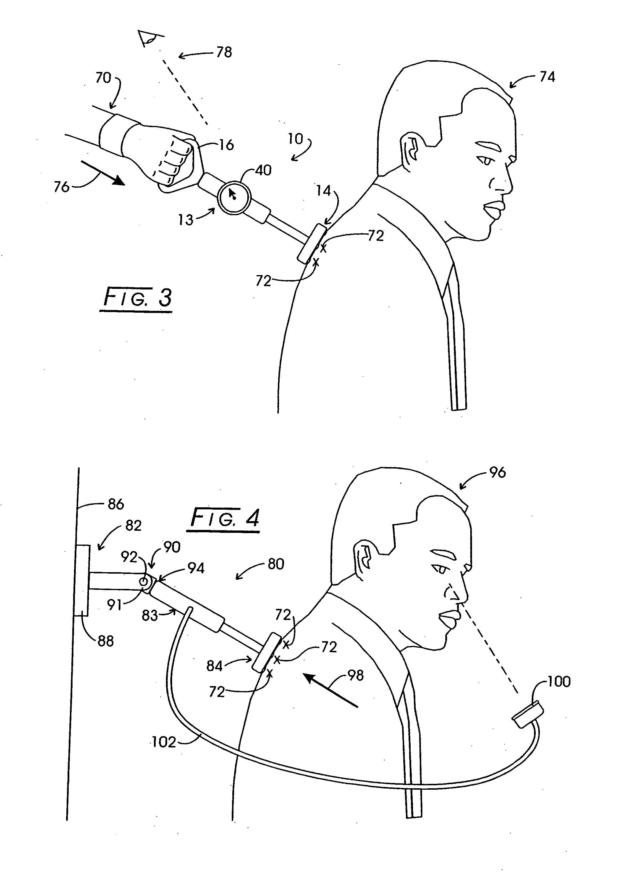
[0083] The method, system and device of the invention can be used for pain diagnosis and evaluation. Thus, the device may be used to evaluate and measure the amount of pain tolerated by a patient, and the quantitative data can be used to analyze the evolution of the disease and or progress of therapy in the future visits.
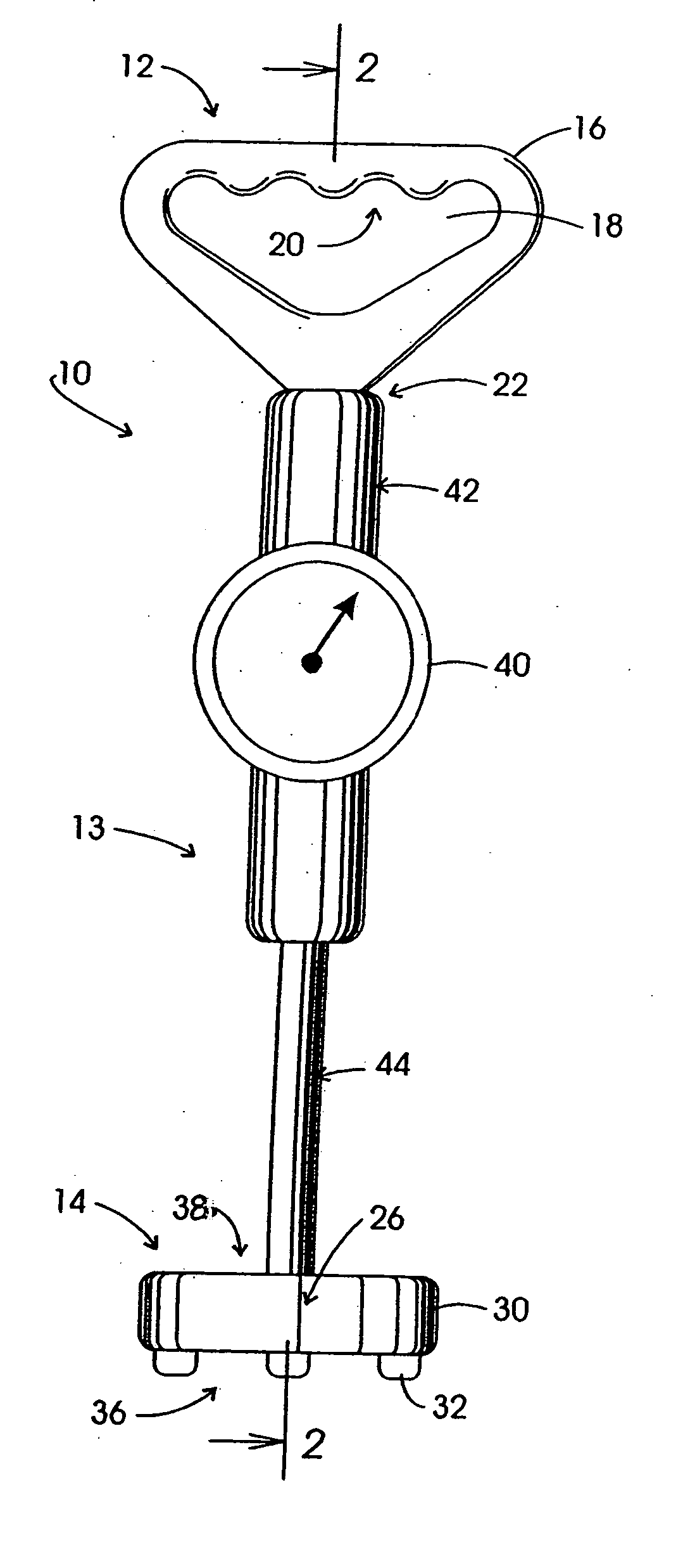
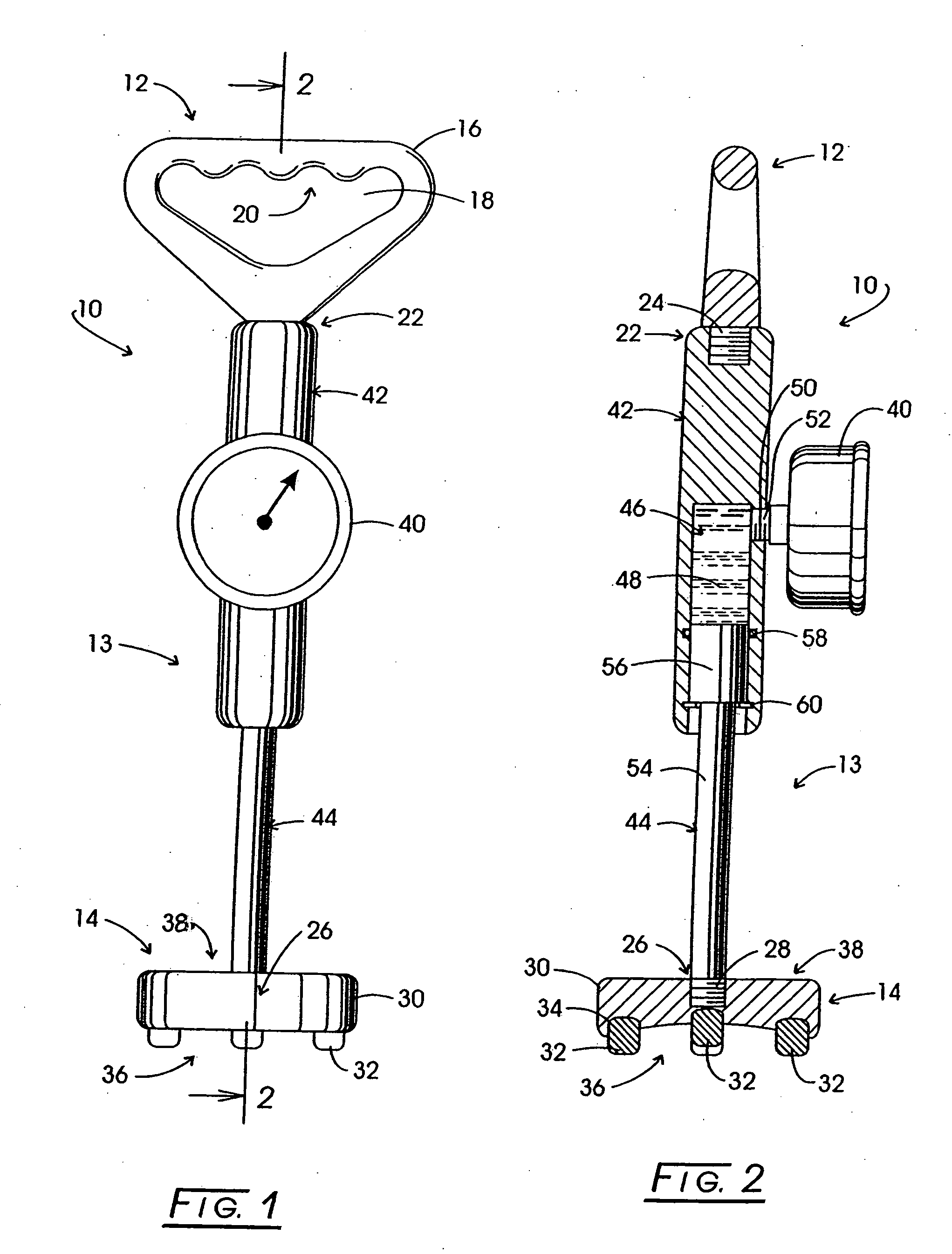
[0084] A device suitable for practicing the CPT therapy is shown in FIGS. 1 and 2. FIG. 1 is a front view of an assembled CPT apparatus 10. FIG. 2 is a sectional view of the device in FIG. 1 though section 2-2. The device is composed of three primary components, a pressure base, shown generally at 12, a pylon, shown generally at 13, and a pressure head, shown generally at 14. The pressure base, 12, is shown embodied in a D-shaped grip, 16, with an opening for the fingers of the therapist at 18, and a portion of the grip formed with ridges, shown generally at 20. Such ridges or other means may assist the therapists in maintaining the position of their hand on the pressure base when pressure is applied to the pressure base. Pressure base 16 is shown to threadably engage an internally threaded cavity, positioned generally at 22, by threaded shaft 24, formed as part of base 16. Those skilled in the art will recognize that pressure base 16 can be modified to accommodate other means of engaging the pylon 13, whether by press fit, snap fit, or integral molding or casting, for instance, of the pressure base as part of the pylon. Any of these means would be capable of transferring applied pressure from the pressure base 12 through the pylon 13 to the pressure head 14. The structure of pressure base 12 can take many forms, as will be disclosed below herein.
[0085] Pressure head 14 is shown in FIGS. 1 and 2 as being generally disk shaped. Head 14 is constructed with a internally threaded cavity, shown generally at 26, that threadably engages external threads 28 on the end of pylon 13. Just as with the engagement of pressure base 12 to pylon 13, those skilled in the art will recognize pressure head 14 can be modified to accommodate other means of engaging the pylon 13, so long as the means employed are capable of transferring applied pressure through the pylon 13 to the pressure head 14. In the particular embodiment shown in FIGS. 1 and 2, pressure head 14 is formed of two types of components: a disk shaped central platform structure 30, and pressure tips 32, with platform 30

Problems solved by technology

They are painful on compression and trigger pain in a referred area.
Nonetheless,

Method used


Image

  • Apparatus, systems, and methods for continuous pressure technique therapy
  • Apparatus, systems, and methods for continuous pressure technique therapy
  • Apparatus, systems, and methods for continuous pressure technique therapy

Examples


example 1

[0121] In FIG. 29, a patient undergoing CPT therapy, 502, reclines on table 504, with table 504 supported by adjustable frame 508. Patient 502 is receiving therapy through means of CPT therapy device 510. Device 510 is positioned and attached to frame 508 through adjustable pressure base 512, pressure is delivered by actuatable pylon 513 through interchangeable pressure head 514 to patient 502. The pylon component is able to apply different levels of pressure based on the therapist-practitioner's professional assessments of the patient's needs to a chosen pressure point represented at 516. Pressure communicating component 540 is capable of delivering pressurized fluid by which to actuate pylon 513. Pressure communicating component 540 receives pressure in communication with pressure controller 542. Pressure controller 542 may be programmed by the practitioner to deliver the desired pressure, by means of controls, represented in general at 544. Controller 542 also displays a remotely...

example 2

Sample Protocols for Utilization of the System and Device of the Invention Including for Use in Rapid Pressure Treatment Modalities

A. Fragile Patient:

[0126] 1. Skin Contact

[0127] 2. Pressure X for 3 seconds (Increase slowly to the 3X pressure point)

[0128] 3. Pressure 3X for 4 seconds;

[0129] 4. Pressure 2X for 34 seconds

B. Normal Patient (Greater pressures could be used)

[0130] 1. Skin Contact

[0131] 2. Pressure X for 3 seconds (Increase slowly to the 3X pressure point)

[0132] 3. Pressure 4X for 6 seconds;

[0133] 4. Pressure 3X for 36 seconds

example 3

Pressure Adaptation in Accordance with the Protocol

[0134] Soft Protocol or sample protocol for limited force application of the system and device of the invention.

[0135] 1. At risk patients: e.g. Osteoporosis patients.

[0136] 1.1 Mild Progressive program: Using the NM Davkor I, apply using a 3 to 5 Kg pressure on the site (using available device). Given that this technique is often painful to sensitive areas, the technique should be applied to an extent that is tolerable to the patient. Maintain the pressure for a few seconds, then reduce the pressure and hold consistently without movement for a period of 15 to 50 seconds. This will produce a feeling of numbness at first, but will slowly reduce or eliminate the pain completely.

[0137] 2. Not at risk patients.

[0138] 2.1 Mild Progressive Program: Using the NM Davkor I, apply using a 4 to 7 Kg pressure on the site (using available device). The technique should be applied to an extent that is tolerable to the patient. Maintain the pr...


PUM


Abstract

The invention provides a device for applying a non-invasive therapeutically reproducible pressure massage to skin and underlying tissues of the animal body. A Continuous Pressure Technique device and fitted attachable accessory components are provided for use with massage therapy on for a variety of target tissues of the patient body. Said accessory components include features allowing the induction of a therapeutically adequate profound pressure with relatively little effort enabling a therapist to treat a number of treatment targets, and a number of patients without excessive fatigue to the therapist. The provided CPT device provides for the capability of remotely determining pressure applied to the patient body simultaneously with use of the device.

Description

[0001] The invention, a Continuous Pressure Therapy, “CPT therapy” method system and device along with accessories supports the therapist by multiplying his exerted force, thus allowing induction of a profound pressure as effortlessly as possible and leading to a reproducible, adequate, quantitative, highly-localized and / or a continuous pressure to any targeted part of body. The devices of the invention can be used with a variety of different types of massage therapy as noted above. Additionally the CPT device used for Continuous Pressure Therapy provides new concepts and therapies for improved patient response and are applicable in the fields of prevention, evaluation and therapy of locomotor diseases. CROSS-REFERENCE TO RELATED APPLICATIONS [0002] This application claims priority to pending European Application No. 05112563.1, filed Dec. 21, 2005. STATEMENT REGARDING FEDERALLY SPONSORED RESEARCH [0003] Not Applicable. BACKGROUND OF THE INVENTION [0004] Massage can be defined as th...

Claims


Application Information

Patent Timeline
IPC IPC(8): A61H7/00A61H15/00
CPCA61H1/008A61H2201/1284A61H39/04A61H7/001A61H2201/1695A61H1/00A61H7/00
Inventor KHORASSANI ZADEH, DAVID
Owner KHORASSANI ZADEH DAVID
Why Eureka
Try Eureka