Method for Minimally Invasive Treatment of Unstable Pelvic Ring Injuries

a pelvic ring and minimally invasive technology, applied in the field of unstable pelvic ring minimally invasive treatment, can solve the problems of acute pelvic fractures, complex fracture types, and potential lethal acute pelvic fractures, and achieve the effect of avoiding potential compressive complications

Active Publication Date: 2012-10-11
VAIDYA RAHUL
View PDF0 Cites 27 Cited by
  • Summary
  • Abstract
  • Description
  • Claims
  • Application Information

AI Technical Summary

Benefits of technology

[0012]The surgical method may further include the steps of: threading a first threaded nut onto each of the threaded rods affixed to each of the first and second ilium of the pelvis; inserting one of the threaded rods affixed to the ilia into the holes in the either end of the elongated plate, the elongated plate resting on the first threaded nuts; threading a second threaded nut onto each of the threaded rods affixed to the ilia; and tightening the second threaded nuts against the elongated anterior plate such that the first threaded nuts and the second threaded nuts hold the elongated anterior plate securely to the threaded rod affixed to the ilia. The elongated anterior plate may have bends to give the plate an approximation of an arc shape. The elongated anterior plate may be positioned with the arc anterior to avoid any potential compressive complications to genitourinary or neurovascular structures prior to the step of attaching.

Problems solved by technology

Unstable pelvic fractures typically occur as a result of high-energy injuries such as automobile accidents, falls and the like.
Even in this age of modern polytrauma care, acute pelvic fractures are potentially lethal.
This type of fracture tends to be more complex with it involving multiple bony structures.
The primary disadvantages of external fixation of pelvic fractures include high risk of pin tract infections, and general patient discomfort.
Also, the external frame physically blocks subsequent surgery on the abdomen and they are frequently difficult to fit to obese patients.

Method used


Image

  • Method for Minimally Invasive Treatment of Unstable Pelvic Ring Injuries
  • Method for Minimally Invasive Treatment of Unstable Pelvic Ring Injuries
  • Method for Minimally Invasive Treatment of Unstable Pelvic Ring Injuries

Examples


first embodiment

Surgical Technique First Embodiment

[0029]The patient may be positioned in the supine position on a radiolucent table. The skin may be prepped and draped from above the umbilicus to the proximal thigh. The lower extremity may be prepped into the field as well to facilitate reduction techniques.

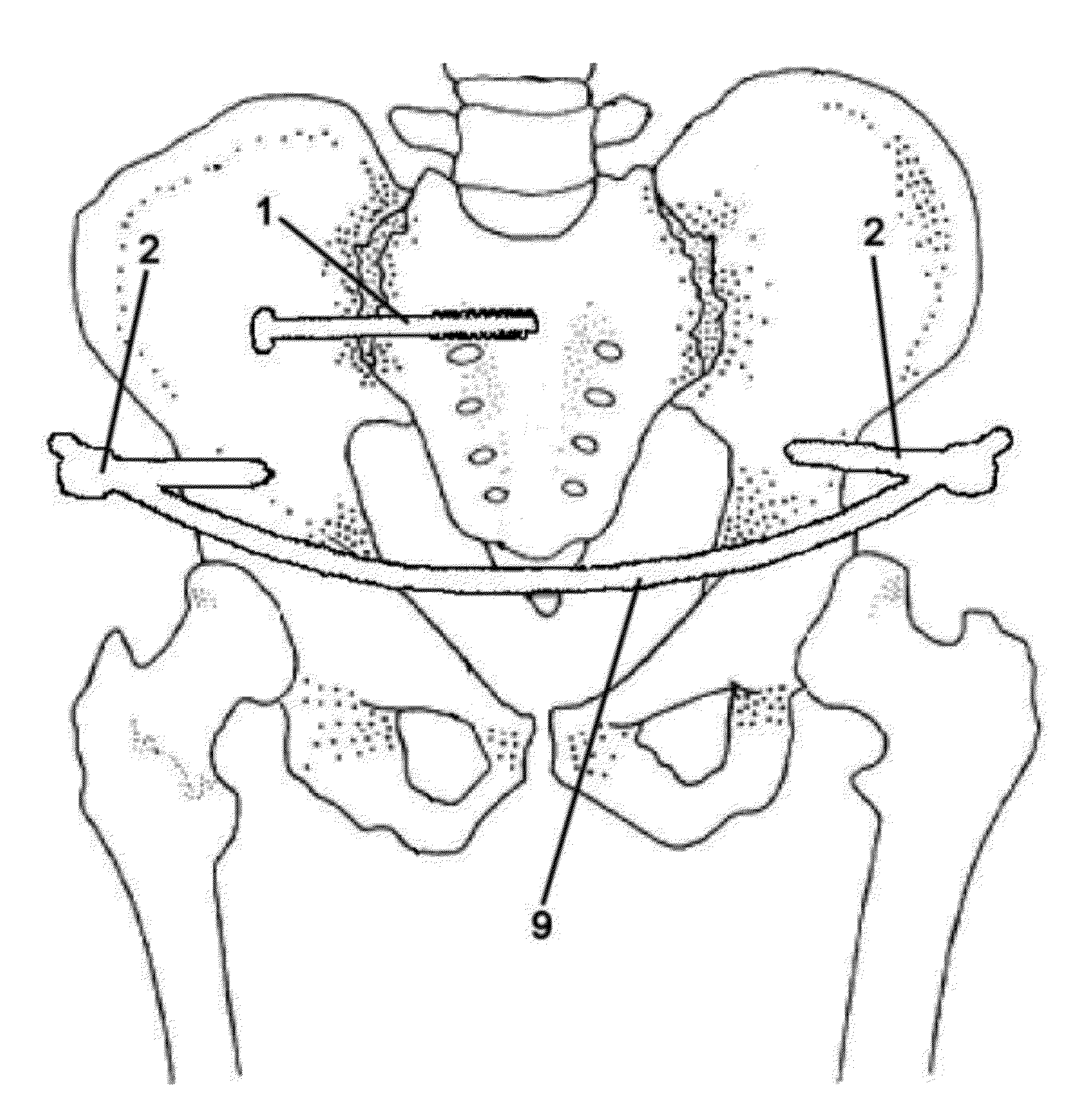
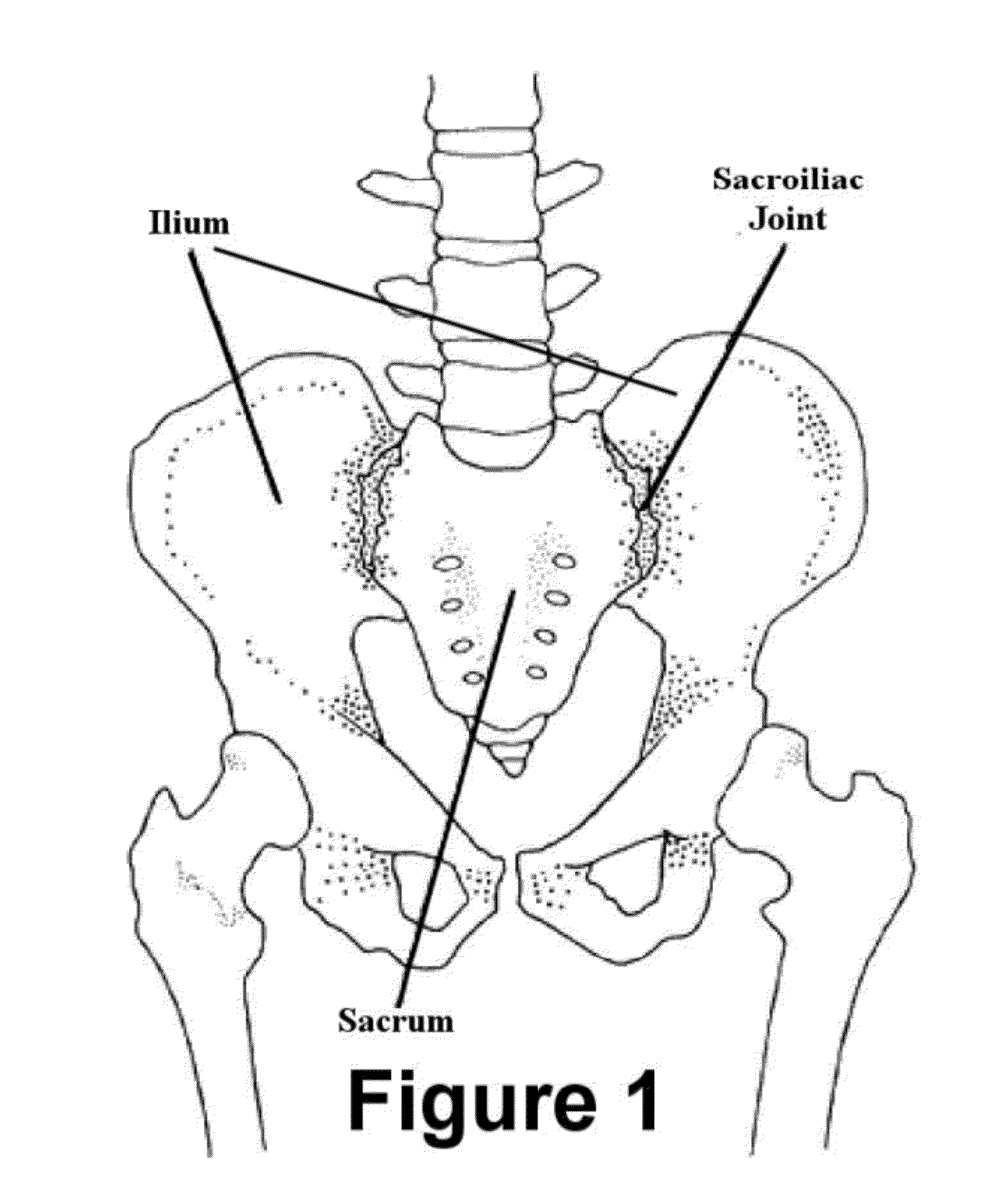
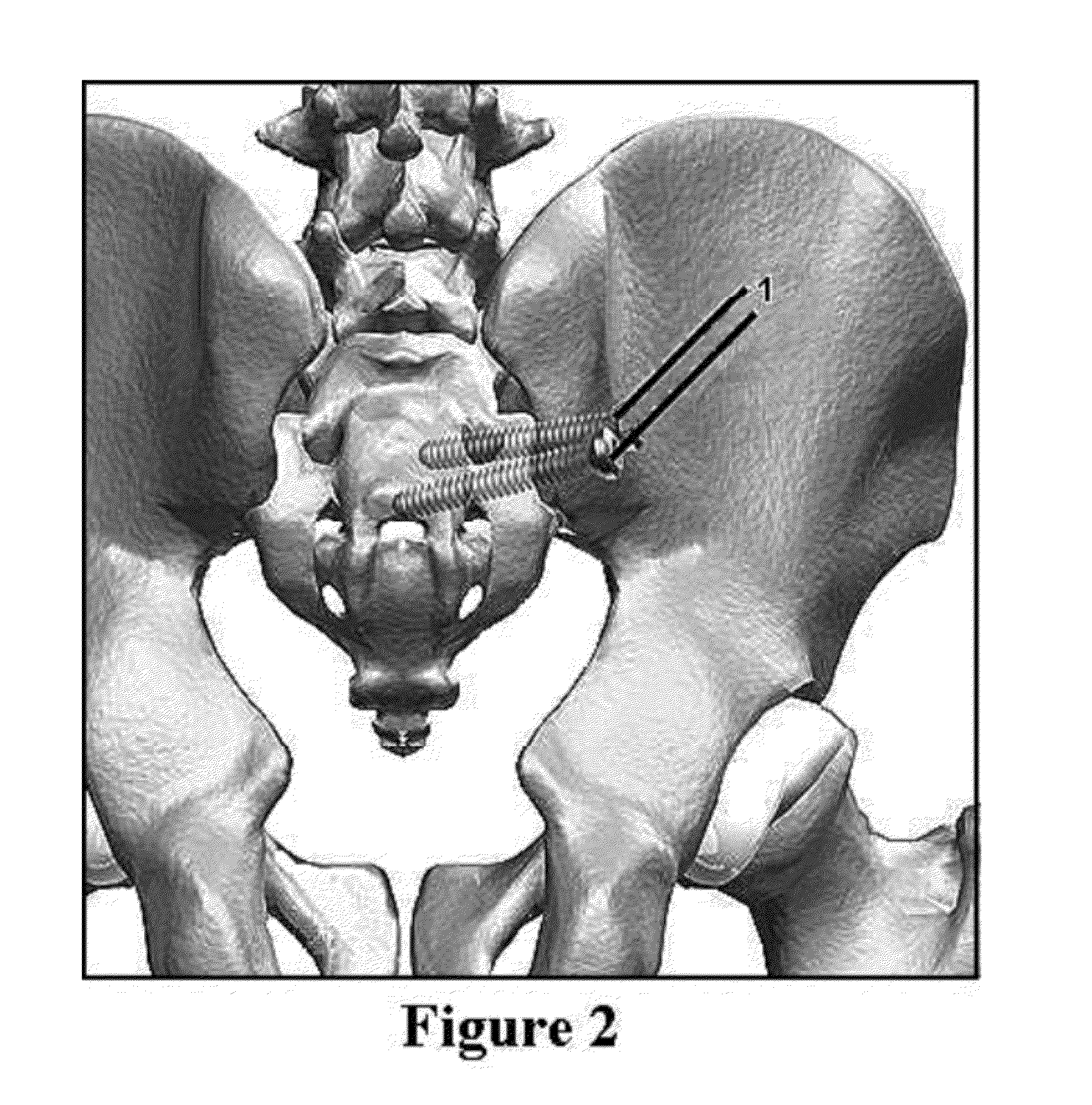
[0030]The posterior instability may be addressed first. The procedure for placement of iliosacral screws for posterior pelvic instability has been well described and will not be discussed here. See for example “CT-Guided Iliosacral Screw Placement: Technique and Clinical Experience” by Robert L. Sciulli, et al., American Journal of Roentgenology 2007; 188:W181-W192 (reproduced at http: / / www.ajronline.org / cgi / content / full / 188 / 2 / W181). FIG. 2 illustrates the way in which iliosacral screws 1 are inserted through the rear of the ilium and into the sacrum, thus stabilizing the posterior instability. FIG. 3 depicts typical iliosacral screws 1.

[0031]After stabilizing the posterior elements via the ili...

second embodiment

Surgical Technique Second Embodiment

[0046]In an alternative embodiment, an anteriorly bowed subcutaneous elongated plate is used in place of the bowed rod. The elongated plate 10 is depicted in FIG. 8a. The plate 10 has at least one hole 11 in each end to accommodate the fixation means which affix the plate to the pelvis. Preferably the at least one hole 11 may be an elongated slot. More preferably the elongated slot is open on one end as shown in FIG. 8a. The elongated plate 10 may be bowed in a continuous arc or may have bends 13 (see FIG. 8b) to give the plate an approximation of an arc shape. The elongated plate 10 may be bent by the surgeon before insertion into the patient or may come pre-bent in a kit along with the fixation means. The pre-bent elongated plate 10 may come in a variety of lengths. It is believed that a most patients needs can be addressed using one size from a group of only three different sizes. The elongated plate 10 has a length much greater that its width ...

third embodiment

Surgical Technique Third Embodiment

[0055]In yet another embodiment, an anteriorly bowed subcutaneous elongated plate is used in place of the bowed rod and a second plate is used on the posterior in place of the iliosacral screws. The two plates are shown in FIGS. 11a-11d. The side view and top view of the posterior plate 10″ are depicted in FIGS. 11a and 11b. The posterior plate 10″ has at least two holes 11 in each end thereof to accommodate the fixation means which affix the plate to the pelvis and the sacrum. The outermost holes 11 will be used to affix the posterior plate 10″ to the ilia of the pelvis. The innermost holes 11 will be used to affix the posterior plate 10″ to the sacrum. The posterior plate 10″ has bends 13 to give the plate a shape that allows for fixation to the ilia of the pelvis and the sacrum, wile pressing against the posterior of the sacrum.

[0056]The side view and top view of the elongated anterior plate 10’ are depicted in FIGS. 11c and 11d. The elongated a...


PUM


Abstract

The instant invention is a novel method for construct for temporary or definitive pelvic stabilization. The method uses the already established principles of anterior external fixation combined with internal hardware placed in a minimally invasive fashion. Fixation means are affixed to the ilia and both a rigid, subcutaneous anteriorly bowed elongated plate and a subcutaneous posterior plate are connected between the fixation means.

Description

RELATED APPLICATIONS[0001]This application is a continuation-in-part of U.S. application Ser. No. 13 / 470,608 filed May 14, 2012 and entitled “Method for Minimally Invasive Treatment of Unstable Pelvic Ring Injuries with an Internal Anterior Fixator and Posterior Iliosacral Screws”, which is a continuation of U.S. application Ser. No. 12 / 287,280 filed Oct. 9, 2008, now U.S. Pat. No. 8,177,785. This application is also a continuation-in-part of U.S. application Ser. No. 12 / 590,988 filed Nov. 18, 2009 and entitled “Method for Minimally Invasive Treatment of Unstable Pelvic Ring Injuries” (now published as U.S. Patent Application Publication number 2010-0198267).FIELD OF THE INVENTION[0002]The instant invention relates generally to methods and apparatus for the treatment of unstable pelvic fractures. More specifically the invention relates to a method and apparatus for minimally invasive treatment of unstable pelvic ring injuries using both anterior and posterior internal fixators.BACKG...

Claims


Application Information

Patent Timeline
Patent Type & Authority Applications(United States)
IPC IPC(8): A61B17/88
CPCA61B17/6433
Inventor VAIDYA, RAHUL
Owner VAIDYA RAHUL
Why Eureka
Try Eureka