Endoscope and optical fiber assembly

a technology of optical fiber and endoscope, which is applied in the field of endoscopes, can solve the problems of affecting the rotational movement of the guide element and the damage of the endoscope, and achieve the effect of limiting the longitudinal limiting the rotational movement of the optical fiber

Active Publication Date: 2007-11-22
BOSTON SCI SCIMED INC
View PDF17 Cites 57 Cited by
  • Summary
  • Abstract
  • Description
  • Claims
  • Application Information

AI Technical Summary

Benefits of technology

[0012]An optical fiber assembly is described that fits within the endoscope, having a fiber end element, such as a side firing tip, with an emission surface through which radiation from the optical fiber is directed into the working region. The endoscope and optical fiber assembly cooperate to maintain the tip of the fiber spaced away from the tissue in the working region by a desired amount to assist management of the energy density delivered to the working region, while preventing the laser energy from being directed away from the working region, particularly to prevent directing laser energy onto the endoscope. A guide element at or near the distal end of the external cannula is adapted to movably support the optical fiber in a position spaced away from the inner wall of the external cannula. Also, the guide element limits lateral movement of the tip without preventing longitudinal movement of the tip within the working region. Also, the guide element does not prevent rotational movement of the tip over at least the predetermined arc.
[0013]An irrigant nozzle element at the end of one of the plurality of tubes at or near the distal end of the external cannula is provided. The irrigant nozzle element having a crescent shaped opening in an implementation described herein at the distal end below the guide element for the optical fiber, is arranged to direct inflowing irrigant over the emission surface of the tip as the tip is moved over a predetermined distance longitudinally into the working region, and as the tip is moved rotationally through the predetermined arc. Also, an irrigant back flow port is included at the distal end which withdraws irrigant from the working region in cooperation with the irrigant nozzle element so that the flow of irrigant over the emission surface of the tip is maintained.
[0014]An optical fiber assembly adapted to work with the endoscope includes an optical fiber as mentioned above having a tip at or near the distal end of the optical fiber. The tip has an emission surface through which radiation from the optical fiber is directed. A fiber port cap, such as a resilient sealing element, is included. The cap has a fiber receiving opening and is adapted to cooperate with and at least partially close a corresponding fiber port on the proximal end of the endoscope. A travel limiter is coupled to the optical fiber at a predetermined distance from the tip of the optical fiber between the fiber port cap and the tip. The travel limiter is adapted to cooperate with a corresponding element in the endoscope, such as a cylindrical bearing surface with a stop element extending into the cylinder, to limit rotational movement of the optical fiber relative to the endoscope to a predetermined arc, and to limit longitudinal movement of the optical fiber relative to the endoscope. In embodiments described herein, the fiber port cap is adapted to act as a stop, in cooperation with the travel limiter and the cylindrical bearing surface in the fiber port, for longitudinal movement of the optical fiber, preventing movement of the emission surface that would withdraw it into the endoscope.

Problems solved by technology

Performing a surgical laser procedure through an endoscope creates several challenges.
Thus, in some high power laser applications, it is possible to damage an endoscope by inadvertently directing laser radiation into the structure.
Also, the guide element does not prevent rotational movement of the tip over at least the predetermined arc.

Method used


Image

  • Endoscope and optical fiber assembly
  • Endoscope and optical fiber assembly
  • Endoscope and optical fiber assembly

Examples


Embodiment Construction

[0034]A detailed description of embodiments of the present invention is provided with reference to the FIGS. 1-19.

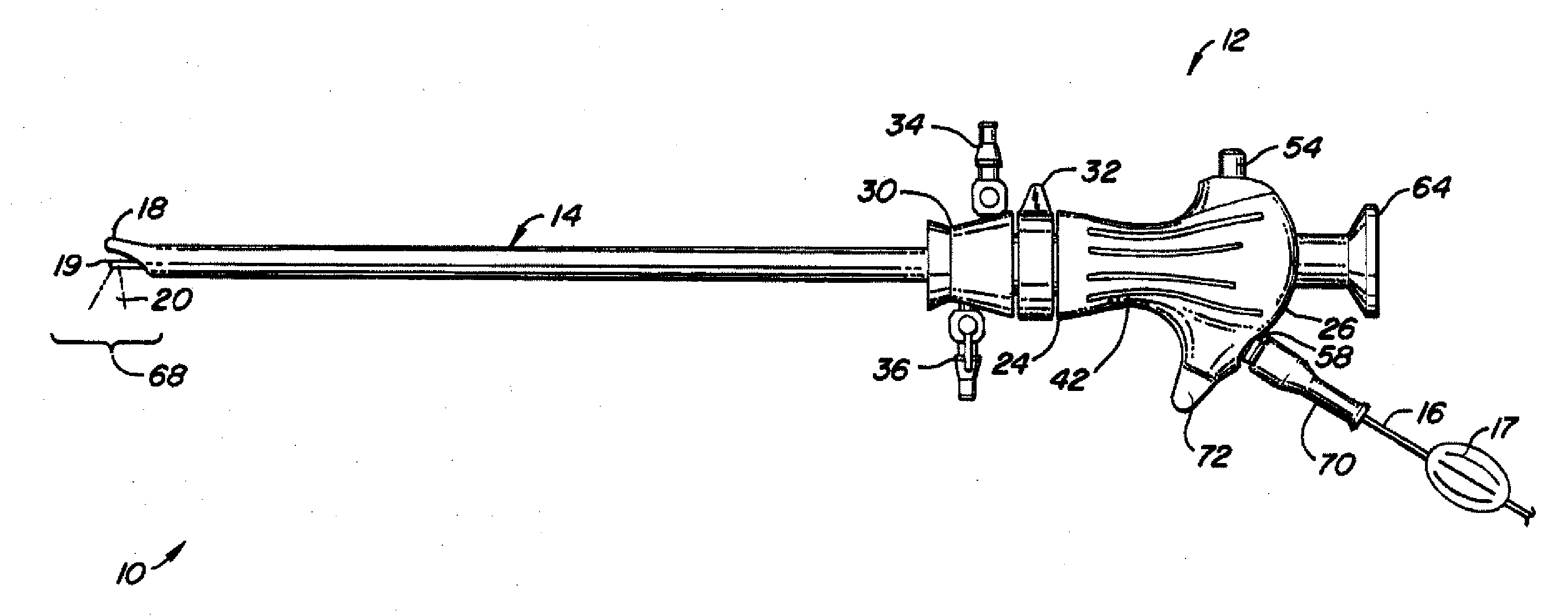
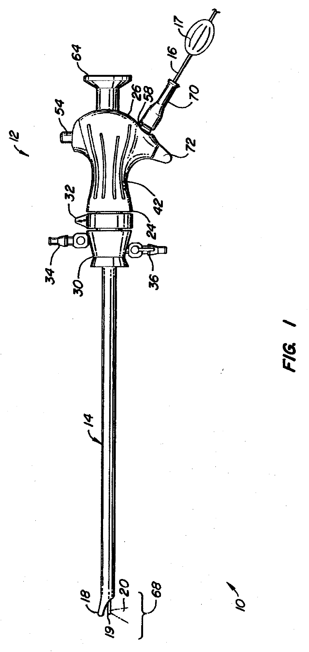
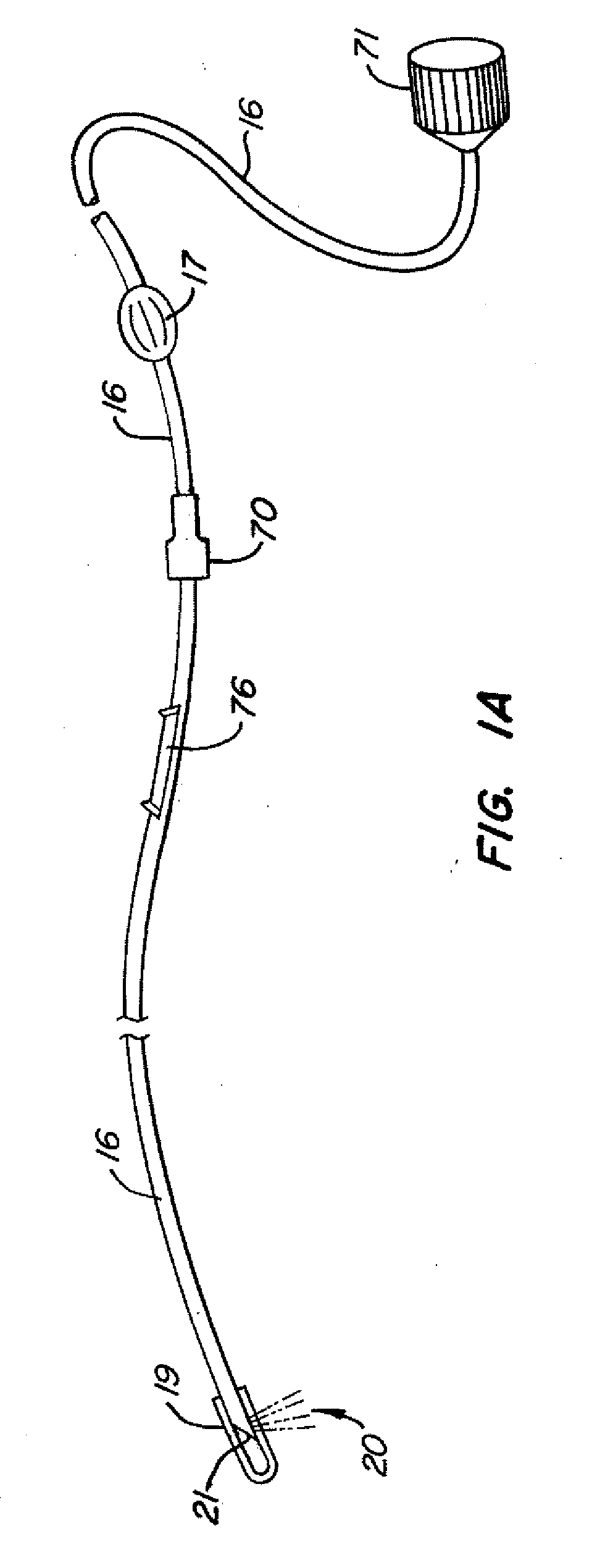
[0035]FIG. 1 illustrates a multifunction endoscope 10, such as a transurethral cystoscope, including a handle 12 with an external cannula 14 extending distally from the handle 12. In this embodiment the multifunction endoscope 10 is designed for use with a medical laser device of the type including an optical fiber 16 having a fiber end member 19 which extends into a cavity formed by a hood structure (described in more detail below) on the distal tip 18 of external cannula 14. The optical fiber 16 has a knob 17 attached near the handle 12 that is adapted to be used by a surgeon to manipulate the position of the fiber end member, rotationally and longitudinally. External cannula 14 has a number of passageways or lumens formed by an internal structure, not shown, extending generally from handle 12 to distal tip 18 to accommodate, in this disclosed embodiment, optical fiber...


PUM


Abstract

An endoscope for an optical fiber provides for inflow and outflow of irrigant. A telescope is included having a field of view directed into a working region. The endoscope defines a “hooded region” with an extended, blunt tip. The optical fiber fits within the endoscope has a side or end firing tip with an emission surface. A guide element is adapted to movably support the optical fiber in a position spaced away from the working region, and limit lateral movement of the tip without preventing longitudinal and rotational movement. An irrigant flow arrangement operates to direct inflowing irrigant over the emission surface of the tip. The fiber is assembled with a fiber coupler, a handle, a fiber port cap, and a travel limiter fixed to the fiber at a predetermined distance from the tip. The travel limiter cooperates with the endoscope and the fiber port cap to limit longitudinal and rotational movement of the fiber.

Description

CROSS-REFERENCE TO RELATED APPLICATIONS[0001]This application claims the benefit of, and incorporates by reference, U.S. Provisional Application No. 60 / 747,780, filed 19 May 2006.BACKGROUND OF THE INVENTION[0002]1. Field of the Invention[0003]The present invention relates generally to endoscopes, and in particular the configuration of a handle used for a multifunction endoscope.[0004]2. Description of Related Art[0005]An endoscope is an illuminated medical device used look inside the body and examine organs. An endoscope can be rigid or flexible. Endoscopes designed for particular procedures often have specialized names, such as cystoscope (urethra, bladder), nephroscope (kidney), bronchoscope (bronchi), laryngoscope (larynx), otoscope (ear), arthroscope (joint) and laparoscope (abdomen). In addition to being used for viewing and examination, endoscopes are often used with various types of medical instruments for diagnostic and therapeutic procedures. An example of these medical ins...

Claims


Application Information

Patent Timeline
Patent Type & Authority Applications(United States)
IPC IPC(8): A61B18/18A61B1/04
CPCA61B1/015A61B1/018A61B1/07A61B1/0017A61B2018/2272A61B2019/304A61B2019/305A61B18/24A61B2090/034A61B2090/035
Inventor NAHEN, KESTERARNOLD, KENPENG, STEVEN YIHLIHKERMODE, JAMES RAYMOND
Owner BOSTON SCI SCIMED INC
Why Eureka
Try Eureka