Signal processing method, signal processing apparatus and recording medium

a signal processing and signal processing technology, applied in the field of signal processing methods and signal processing apparatuses, can solve the problems of energy loss of user dissatisfaction with acoustic signals or image signals, and patent documents 1 to 3 do not offer means for solving such problems, so as to eliminate dissatisfaction

Inactive Publication Date: 2007-11-22
SHARP KK
View PDF18 Cites 7 Cited by
  • Summary
  • Abstract
  • Description
  • Claims
  • Application Information

AI Technical Summary

Benefits of technology

[0018]The present invention has been made with the aim of solving the above problems. An object of the present invention is to provide: a signal processing method and a signal processing apparatus for computing a correction coefficient based on white noise outputted from a white noise storage and a level of a coefficient of a dequantized acoustic signal, computing a correction value by multiplying the white noise by the correction coefficient and adding the correction value to a coefficient so as to interpolate energy lost at the time of coding, eliminate dissatisfaction associated with energy shortage and deal with various coding methods in decoding; and a computer-readable recording medium which records therein a program for causing a computer to function as the signal processing apparatus.

Problems solved by technology

However, in the technique wherein an acoustic signal or an image signal is quantized in the process of coding, there is a problem that rounding or round-down by dequantization may cause energy loss of the acoustic signal or the image signal.
Therefore, the user may feel dissatisfaction at the acoustic signal or the image signal due to the energy loss even at the time of decoding.
Patent Documents 1 to 3 do not offer means for solving such a problem.
Furthermore, it is also necessary to provide a power adjustment information decoding circuit in a decoding apparatus and decode the coded power adjustment information, and there is a problem that interpolation of energy cannot be performed at all for an acoustic signal for which such power adjustment information is not stored.
Especially, since coding methods associated with various specifications are made indiscriminately in recent years, there is a problem that the technique described in Patent Document 4 cannot suitably interpolate a coded acoustic signal or a coded image signal of various methods.

Method used


Image

  • Signal processing method, signal processing apparatus and recording medium
  • Signal processing method, signal processing apparatus and recording medium
  • Signal processing method, signal processing apparatus and recording medium

Examples


embodiment 1

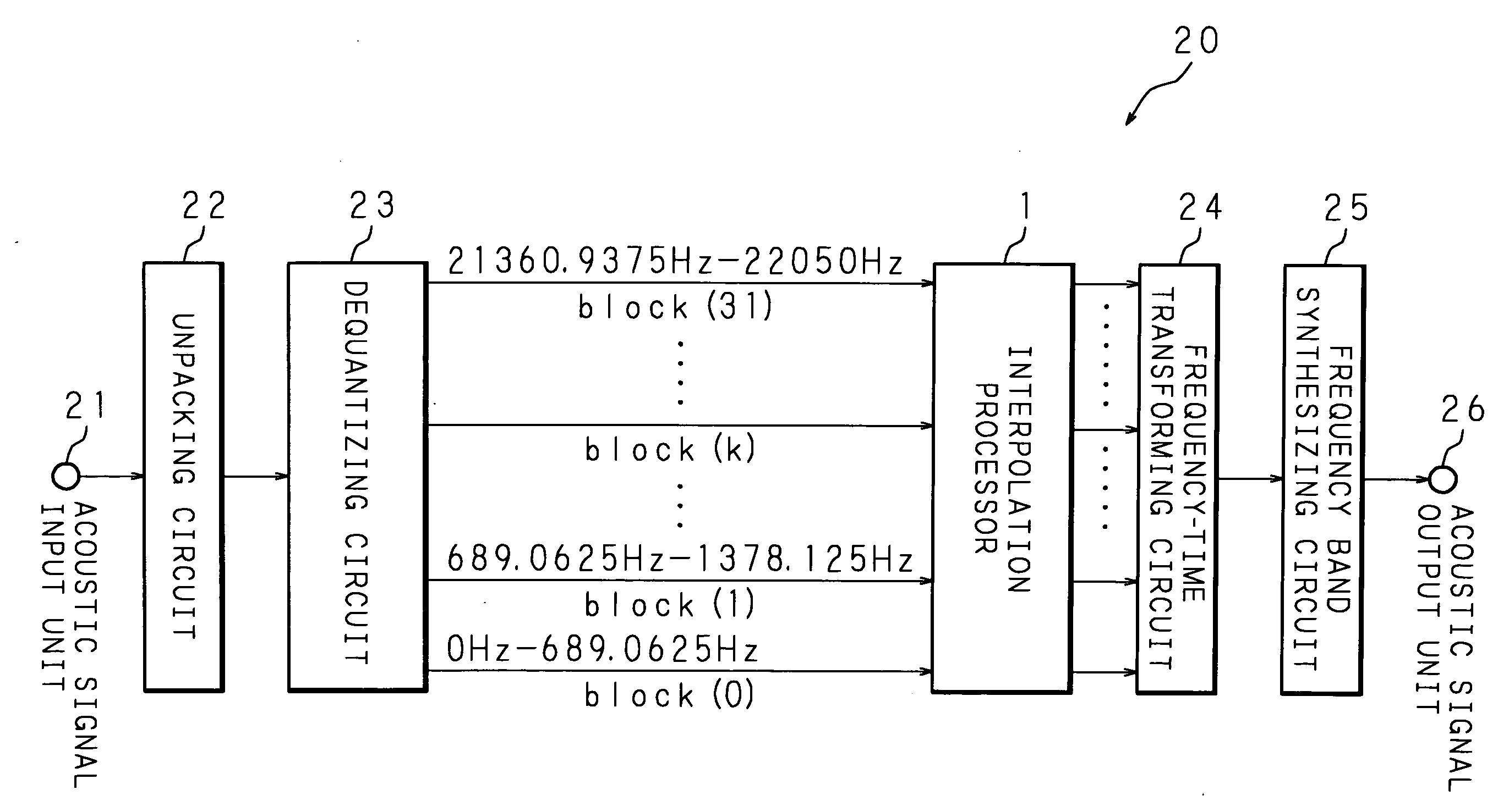
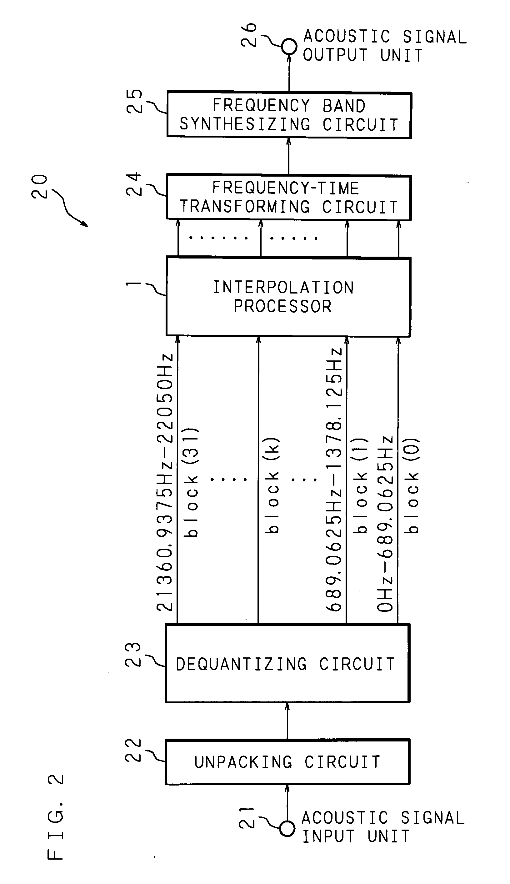
[0091]The following description will explain an embodiment of the present invention with reference to the drawings. FIG. 2 is a block diagram showing the hardware structure of a decoding apparatus which is a signal processing apparatus. Denoted at 20 in the figure is a decoding apparatus for decoding a coded acoustic signal and comprises an acoustic signal input unit 21, an unpacking circuit 22, a dequantizing circuit 23, an interpolation processor 1, a frequency-time transforming circuit 24, a frequency band synthesizing circuit 25 and an acoustic signal output unit 26. It should be noted that, though the present embodiment is explained using an example wherein the MP3 is applied as a compression coding method, other methods may be applied similarly.

[0092]A coded acoustic signal read out from recording medium, a coded acoustic signal received by a digital tuner or the like is inputted into the acoustic signal input unit 21 and the inputted coded acoustic signal is outputted to the ...

embodiment 2

[0107]Embodiment 2 relates to a form for correcting a minimum value detected by a minimum value detecting circuit 12. FIG. 7 is a block diagram showing the hardware structure of an interpolation processor 1 according to Embodiment 2. The interpolation processor 1 according to Embodiment 2 comprises an energy computing circuit 121, a previous frame energy saving circuit 122, an energy change rate computing circuit 123, a determining circuit 124, a minimum value correcting circuit 126, a minimum value change rate computing circuit 125, a correction minimum value setting circuit 127, a minimum value setting circuit 128 and a previous frame minimum value saving circuit 129, in addition to the structure of Embodiment 1. It should be noted that a frame, which means a time interval of a unit of coding (decoding) processing, processed a time corresponding to one frame before a frame which is now being processed is hereinafter referred to as a previous frame.

[0108]A coefficient I(m) of a fre...

embodiment 3

[0133]FIG. 11 is a block diagram showing the structure of a signal processing apparatus 20 according to Embodiment 3. Each process of the signal processing apparatus 20 according to Embodiment 3 may be realized by software executed by a personal computer. The following description will explain an example wherein the signal processing apparatus 20 is a personal computer 20. The personal computer 20 is a known computer comprising: a CPU (Central Processing Unit) 61; and a RAM (Random Access Memory) 62, a memory 65 such as a hard disk, an input unit 63, an output unit 64 such as a speaker and a communication unit 66, which can be connected with a communication network such as the Internet, that are connected with the CPU 61 via a bus 67.

[0134]A computer program for causing the personal computer 20 to operate can be provided in the form of a portable recording medium 1A such as a CD-ROM, an MO or a DVD-ROM as in the present Embodiment 3. Furthermore, it is also possible to download the ...


PUM


Abstract

The minimum value detecting circuit detects a minimum value, excluding zero, of a coefficient according to a dequantized acoustic signal. The correction coefficient computing circuit computes a correction coefficient based on the minimum value and white noise outputted from the white noise storage which stores white noise. In this process, a correction coefficient is computed by, for example, dividing the minimum value obtained by the minimum value detecting circuit by a value which is twice the maximum value or the mean value of white noise stored in the white noise storage. The correction value computing circuit computes a correction value by multiplying the correction coefficient computed by the correction coefficient computing circuit by white noise stored in the white noise storage. A corrected coefficient is computed by adding the correction value obtained as described above to a frequency band having a null coefficient according to a dequantized acoustic signal.

Description

CROSS-REFERENCE OF RELATED APPLICATION[0001]This Nonprovisional Application claims priority under 35 U.S.C.§119(a) on Patent Application No. 2006-139400 in Japan on May 18, 2006, Patent Application No. 2006-139401 in Japan on May 18, 2006, and Patent Application No. 2006-139402 in Japan on May 18, 2006, the entire contents of which are hereby incorporated by reference.BACKGROUND OF THE INVENTION[0002]1. Field of the Invention[0003]The present invention relates to a signal processing method and a signal processing apparatus for processing an acoustic signal obtained by dequantizing a coded acoustic signal and a computer-readable recording medium which records therein a program for causing the signal processing apparatus to function as a computer.[0004]2. Description of the Prior Art[0005]Known as a technique for coding an acoustic signal is MP3 (MPEG 1 Audio Layer 3), AAC (Advanced Audio Coding), ATRAC (Adaptive TRansform Acoustic Coding), WMA (Windows (registered trademark) Media Au...

Claims


Application Information

Patent Timeline
Patent Type & Authority Applications(United States)
IPC IPC(8): G06F17/00G10L19/02G10L19/032G10L21/02
CPCG10L21/0364G10L19/032
Inventor FUJII, OSAMU
Owner SHARP KK
Why Eureka
Try Eureka