Optical position measuring arrangement

a technology of optical positioning and positioning measurement, which is applied in the direction of measurement devices, conversion of sensor output, apparel, etc., can solve the problems of large scanning gap disadvantageous to the installation tolerance of the position measuring device, and large scanning gap requires an elaborate collimation

Active Publication Date: 2007-11-29
DR JOHANNES HEIDENHAIN GMBH
View PDF11 Cites 7 Cited by
  • Summary
  • Abstract
  • Description
  • Claims
  • Application Information

AI Technical Summary

Benefits of technology

[0008] It is therefore an object of the present invention to disclose an optical position measuring arrangement

Problems solved by technology

However, narrower deflection angles of the partial light beams employed for reference signal generation entail problems in connection with certain scanning principles.
In the case of very narrow deflection angles of the partial light beam employed for the reference signal generation, this can only be assured if a

Method used


Image

  • Optical position measuring arrangement
  • Optical position measuring arrangement
  • Optical position measuring arrangement

Examples


Embodiment Construction

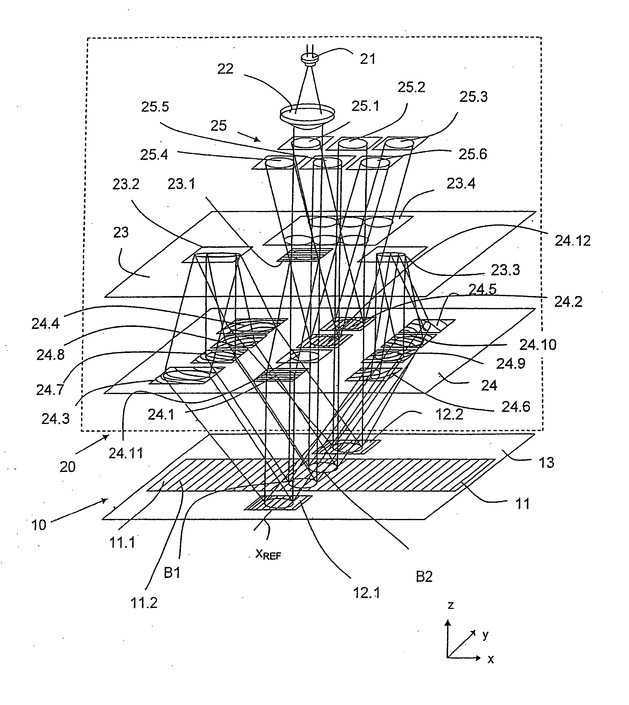
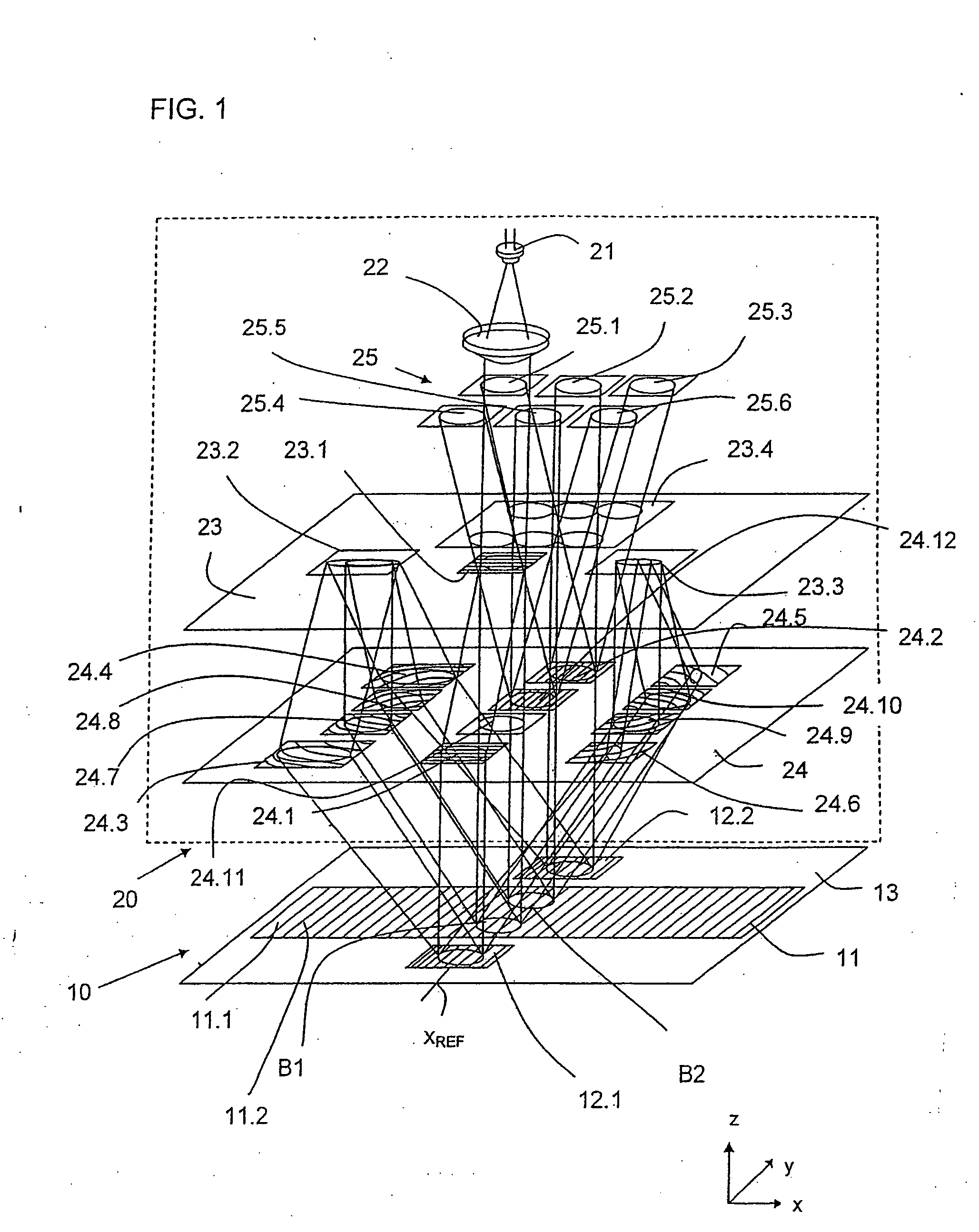
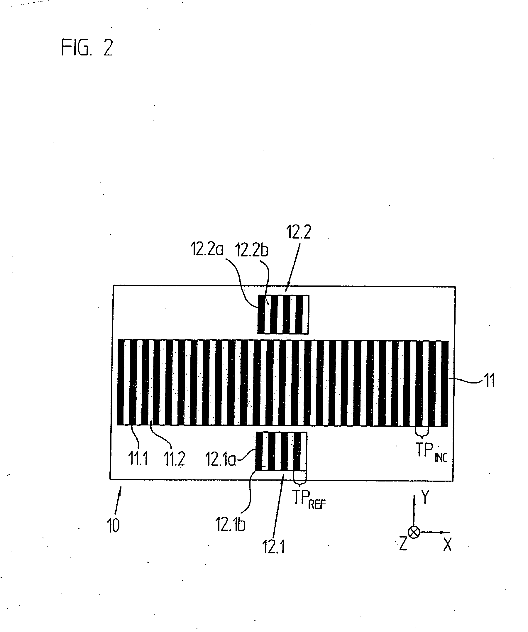
[0036] A first exemplary embodiment of a position measuring arrangement in accordance with the present invention will be explained by FIGS. 1, 2, as well as 3a, 3b, in particular the scanning beam paths provided therein. In a schematic form, FIG. 1 shows the scanning beam paths of this example in a perspective representation, FIG. 2 a view from above on the inserted scale, FIGS. 3a and 3b each a view from above on the top and underside of the scanning plate used.

[0037] It should be pointed out here that the dimensions in accordance with the present invention of the mean graduation period of the reference marking within the range of the graduation period of the used incremental graduation is of course not limited to the below explained optical scanning principle of this exemplary embodiment. Therefore the steps in accordance with the present invention in regard to reference signal generation can also be employed with alternative scanning beam paths.

[0038] In the exemplary embodimen...


PUM


Abstract

An optical position measuring arrangement for detecting the position of a first object and a second object which are movable in relation to each other in a measuring direction. The optical position measuring arrangement including a scale which is connected with the first object, the scale including an incremental graduation extending in the measuring direction and having the graduation period (TPINC). The optical position measuring arrangement including a reference marking at a reference position, wherein the reference marking includes a structure with a graduation period (TPREF), which changes locally, wherein the reference marking has a mean graduation period (TPREF,m) within a range of the graduation period (TPINC) of the incremental graduation. A scanning unit connected with the second object and including a scanning system for generating a reference signal at the reference position.

Description

[0001] Applicant claims, under 35 U.S.C. § 119, the benefit of priority of the filing date of May 9, 2006 of a German patent application, copy attached, Serial Number 10 2006 021 484.6, filed on the aforementioned date, the entire contents of which is incorporated herein by reference. BACKGROUND OF THE INVENTION [0002] 1. Field of the Invention [0003] The present invention relates to an optical position measuring arrangement for detecting the position of two objects which are movable in relation to each other in at least one measuring direction, and have a scale connected with one of the two objects, and a scanning unit connected with the other one of the two objects. [0004] 2. Discussion of Related Art [0005] An optical position measuring arrangement in accordance with the species is known from EP 513 427 B1 of Applicant. It is suitable for detecting the position of two objects which are movable in relation to each other in at least one measuring direction. For this purpose, the kn...

Claims


Application Information

Patent Timeline
IPC IPC(8): G01D5/347
CPCG01D5/38G01D5/36
Inventor HOLZAPFEL, WOLFGANG
Owner DR JOHANNES HEIDENHAIN GMBH
Why Eureka
Try Eureka