Method and apparatus for actively controlling fuel flow to a mixer assembly of a gas turbine engine combustor

Active Publication Date: 2007-11-29
GENERAL ELECTRIC CO
View PDF16 Cites 76 Cited by
  • Summary
  • Abstract
  • Description
  • Claims
  • Application Information

AI Technical Summary

Benefits of technology

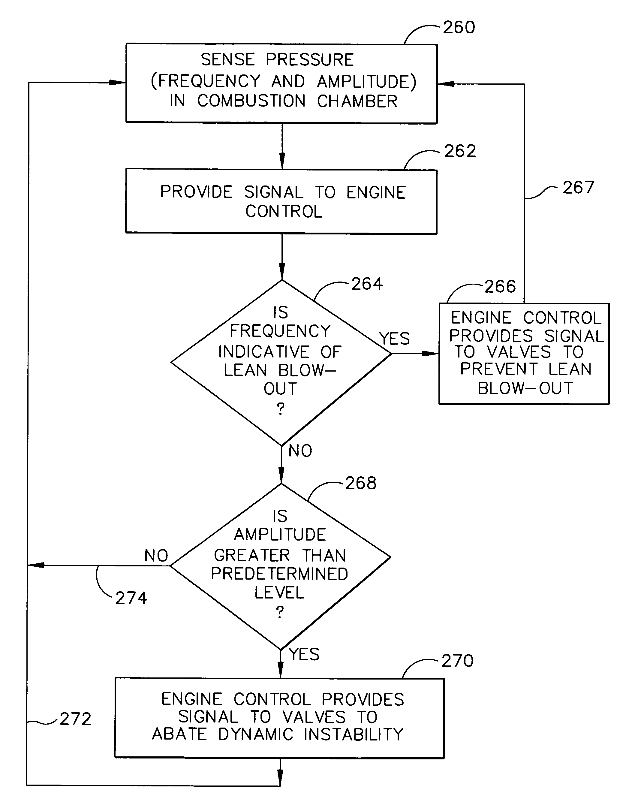
[0010]In a first exemplary embodiment of the invention, an apparatus for actively controlling fuel flow from a fuel pump to a mixer assembly of a gas turbine engine combustor is disclosed, where the mixer assembly includes a pilot mixer and a main mixer. The pilot mixer further includes an annular pilot housing having a hollow interior, a primary fuel injector mounted in the pilot housing and adapted for dispensing droplets of fuel to the hollow interior of the pilot housing, and a plurality of axial swirlers positioned upstream from the primary fuel injector. The fuel flow control appar

Problems solved by technology

Therefore, different combustor designs have been developed to meet those criteria For example, one way in which the problem of minimizing the emission of undesirable gas turbine engine combustion products has been attacked is the provision of staged combustion.
It will be appreciated that balancing the operation of the first and second stage burners to allow efficient thermal operation of the engine, while simultaneously minimizing the production of undesirable combustion products, is difficult to achieve.
In that regard, operating at low combustion temperatures to lower

Method used


Image

  • Method and apparatus for actively controlling fuel flow to a mixer assembly of a gas turbine engine combustor
  • Method and apparatus for actively controlling fuel flow to a mixer assembly of a gas turbine engine combustor
  • Method and apparatus for actively controlling fuel flow to a mixer assembly of a gas turbine engine combustor

Examples


Embodiment Construction

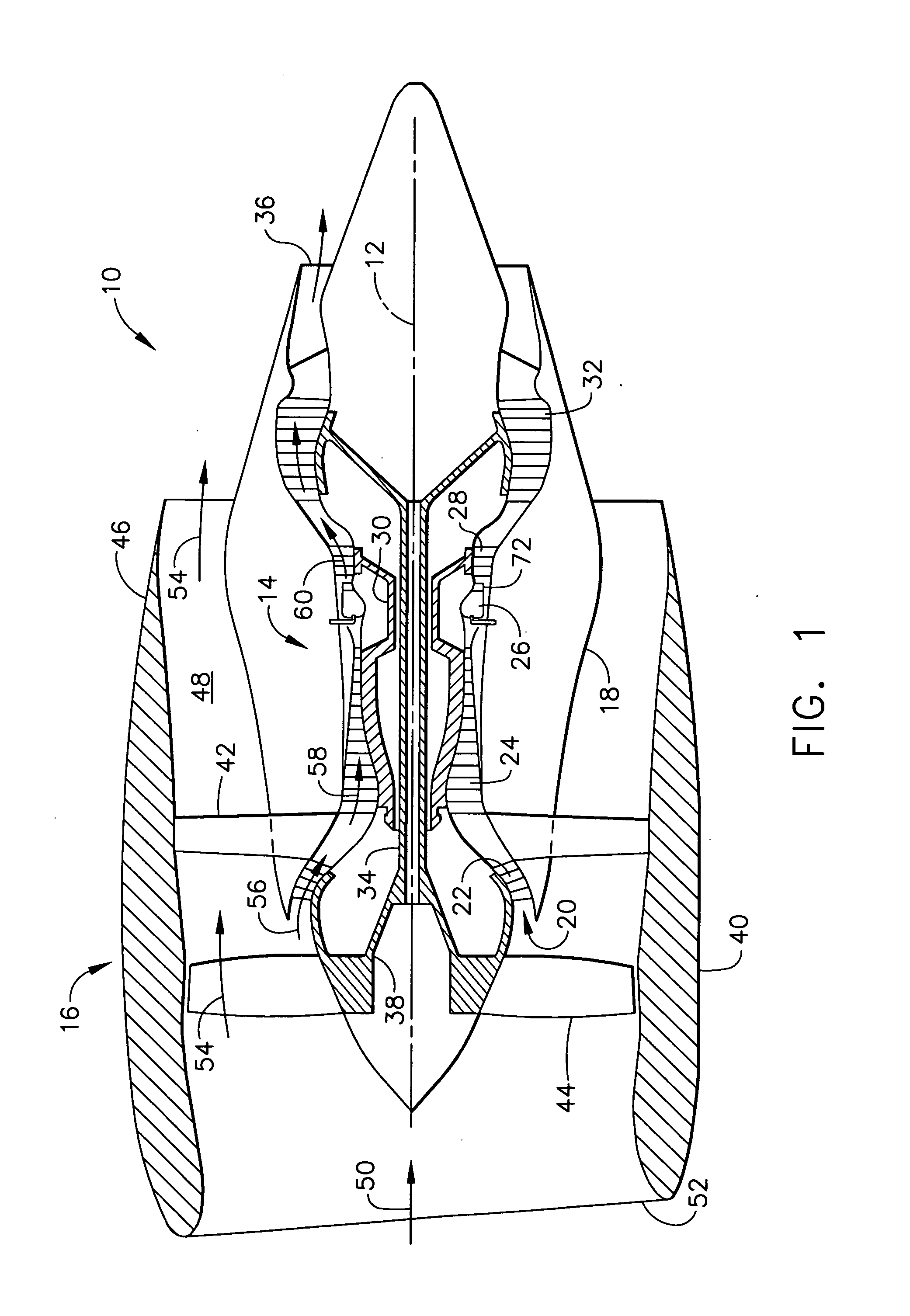
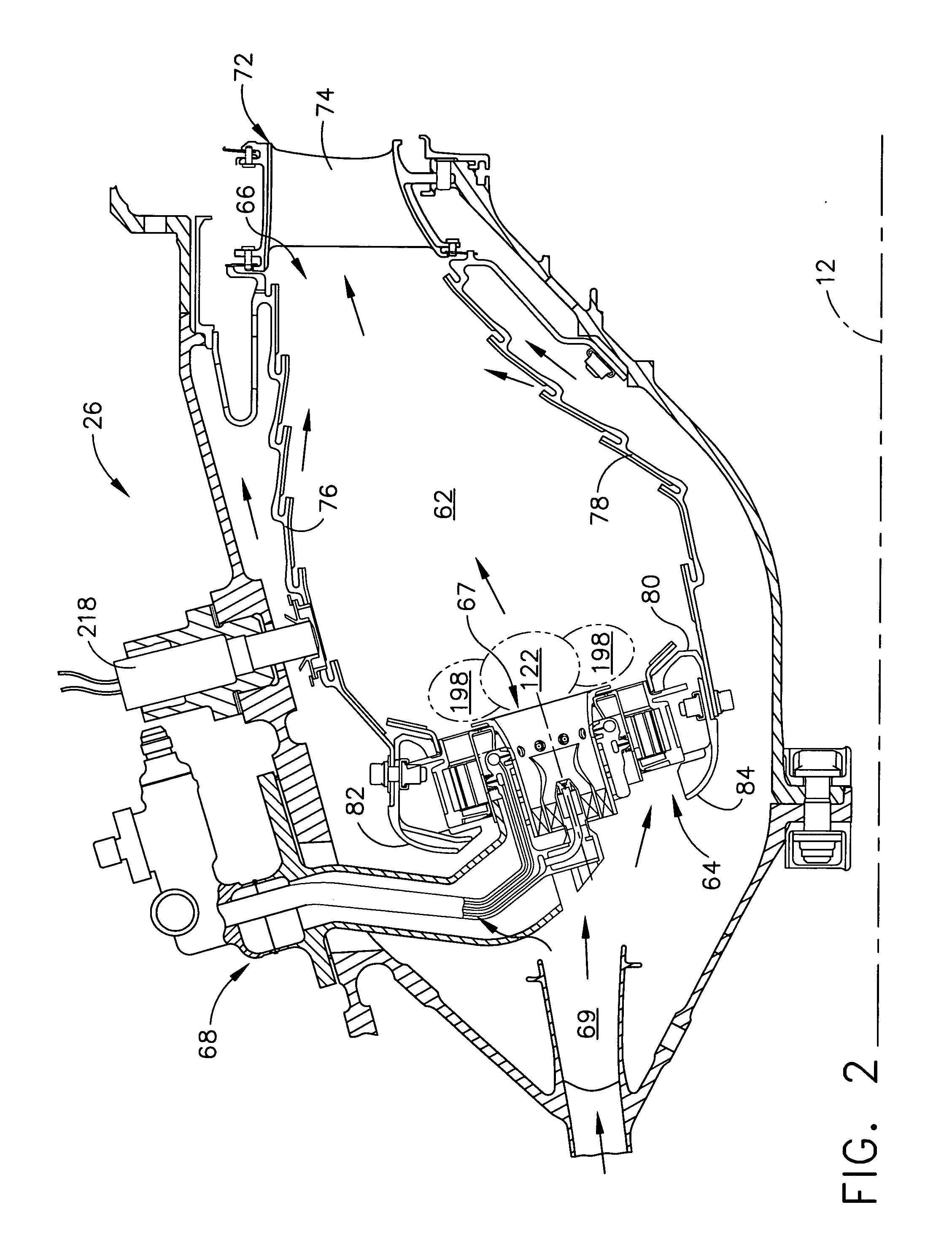
[0025]Referring now to the drawings in detail, wherein identical numerals indicate the same elements throughout the figures, FIG. 1 depicts in diagrammatic form an exemplary gas turbine engine 10 (high bypass type) utilized with aircraft having a longitudinal or axial centerline axis 12 therethrough for reference purposes. Engine 10 preferably includes a core gas turbine engine generally identified by numeral 14 and a fan section 16 positioned upstream thereof. Core engine 14 typically includes a generally tubular outer casing 18 that defines an annular inlet 20. Outer casing 18 further encloses and supports a booster compressor 22 for raising the pressure of the air that enters core engine 14 to a first pressure level. A high pressure, multi-stage, axial-flow compressor 24 receives pressurized air from booster 22 and further increases the pressure of the air. The pressurized air flows to a combustor 26, where fuel is injected into the pressurized air stream to raise the temperature...


PUM


Abstract

An apparatus for actively controlling fuel flow from a fuel pump to a mixer assembly of a gas turbine engine combustor, where the mixer assembly includes a pilot mixer and a main mixer. The pilot mixer further includes an annular pilot housing having a hollow interior, a primary fuel injector mounted in the pilot housing and adapted for dispensing droplets of fuel to the hollow interior of the pilot housing, a plurality of axial swirlers positioned upstream from the primary fuel injector. The fuel flow control apparatus further includes: at least one sensor for detecting dynamic pressure in the combustor; a fuel nozzle; and, a system for controlling fuel flow supplied by the fuel nozzle through the valves. The fuel nozzle includes: a feed strip with a plurality of circuits for providing fuel to the pilot mixer and the main mixer; and, a plurality of valves associated with the fuel nozzle and in flow communication with the feed strip thereof. The control system activates the valves in accordance with signals received from the pressure sensor.

Description

BACKGROUND OF THE INVENTION[0001]The present invention relates to a staged combustion system in which the production of undesirable combustion product components is minimized over the engine operating regime and, more particularly, to a method and apparatus for actively controlling fuel flow to a mixer assembly having a pilot mixer with a primary fuel injector and secondary fuel injection ports.[0002]Modern day emphasis on minimizing the production and discharge of gases that contribute to smog and to other undesirable environmental conditions, particularly those gases that are emitted from internal combustion engines, have led to different gas turbine engine combustor designs that have been developed in an effort to reduce the production and discharge of such undesirable combustion product components. Other factors that influence combustor design are the desires of users of gas turbine engines for efficient, low cost operation, which translates into a need for reduced fuel consumpt...

Claims


Application Information

Patent Timeline
IPC IPC(8): F02C7/26
CPCF02C9/28F23R3/286F23R3/346F23R2900/00013
Inventor MYERS, WILLIAM JOSEPHMANCINI, ALFRED ALBERTHSIAO, GEORGE CHIA-CHUN
Owner GENERAL ELECTRIC CO
Why Eureka
Try Eureka