Variable valve actuator with latch at one end

a variable valve actuator and latch technology, applied in the field of actuators, can solve the problems of inability to meet the valve actuation system, the opening window of the cross-over valve has to be extremely narrow, etc., and achieves the effect of less energy for the snubbing mechanism to dissipate, improved soft seating, and efficient energy conversion

Inactive Publication Date: 2007-11-29
LGD TECH LLC
View PDF3 Cites 21 Cited by
  • Summary
  • Abstract
  • Description
  • Claims
  • Application Information

AI Technical Summary

Benefits of technology

[0007]In operation, the spring subsystem, the actuation piston, and the actuator load (e.g., an engine valve) work as a spring-mass pendulum system, efficiently converting, the potential energy in the spring subsystem to the kinetic energy in the moving mass and vice versa. The efficient energy conversion also leaves less energy for the snubbing mechanism to dissipate and provides better soft seating for the engine valve. The actuation efficiency is also greatly helped by the flow bypass, which, when effective, is able to minimize fluid flow and energy consumption. The system is able to latch the actuation piston at its second direction end position while making it possible for the actuation piston not to dwell at its first direction end position, thus reducing the overall actuation time. The actuator can be supplied and controlled by a 4-way actuation switch valve, two actuation 3-way valves, or one actuation 3-way valve.
[0008]In another embodiment, the second flow mechanism is always wide open, whereas the first flow mechanism is open and closed when the flow bypass is closed and open, respectively. The system is able to latch the actuation piston at its first direction end position while making it possible for the-piston not to dwell at its second direction end position.
[0009]In another embodiment, a spring controller allows the engine valve to close at power-off and provides a means for an effective start-up.
[0010]The present invention provides significant advantages over the prevailing fluid actuators and their control. Its ability to latch the actuator only at one end and allow a quick return motion at the other end greatly saves actuation time, which is important or critical in many applications, especially for the cross-over valve in an air hybrid engine. The fluid nature of the actuator provides high force and power density to deal with the demanding requirements, and yet the bypass mechanism is able to offer high energy efficiency. The control approaches associated with various switch valves are able to deal varying application needs, especially those for an air hybrid engine. With its pendulum arrangement, there is a centering or returning spring force available, in addition to a differential fluid force, to help open the engine valve.

Problems solved by technology

Also, the opening window of the cross-over valve has to be extremely narrow, especially at medium and high engine speeds.
In summary, the cross-over valve actuator has to offer a large opening force, a substantial seating force, a reasonable seating velocity, a high actuation speed, and timing flexibility while consuming minimum energy by itself Most, if not all, engine valve actuation systems are not able to meet these demands.

Method used


Image

  • Variable valve actuator with latch at one end
  • Variable valve actuator with latch at one end
  • Variable valve actuator with latch at one end

Examples


Embodiment Construction

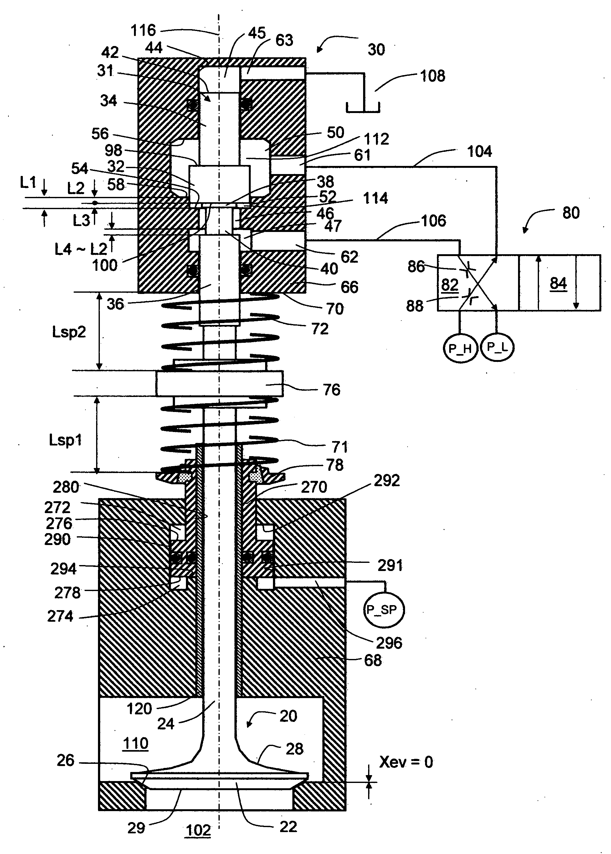
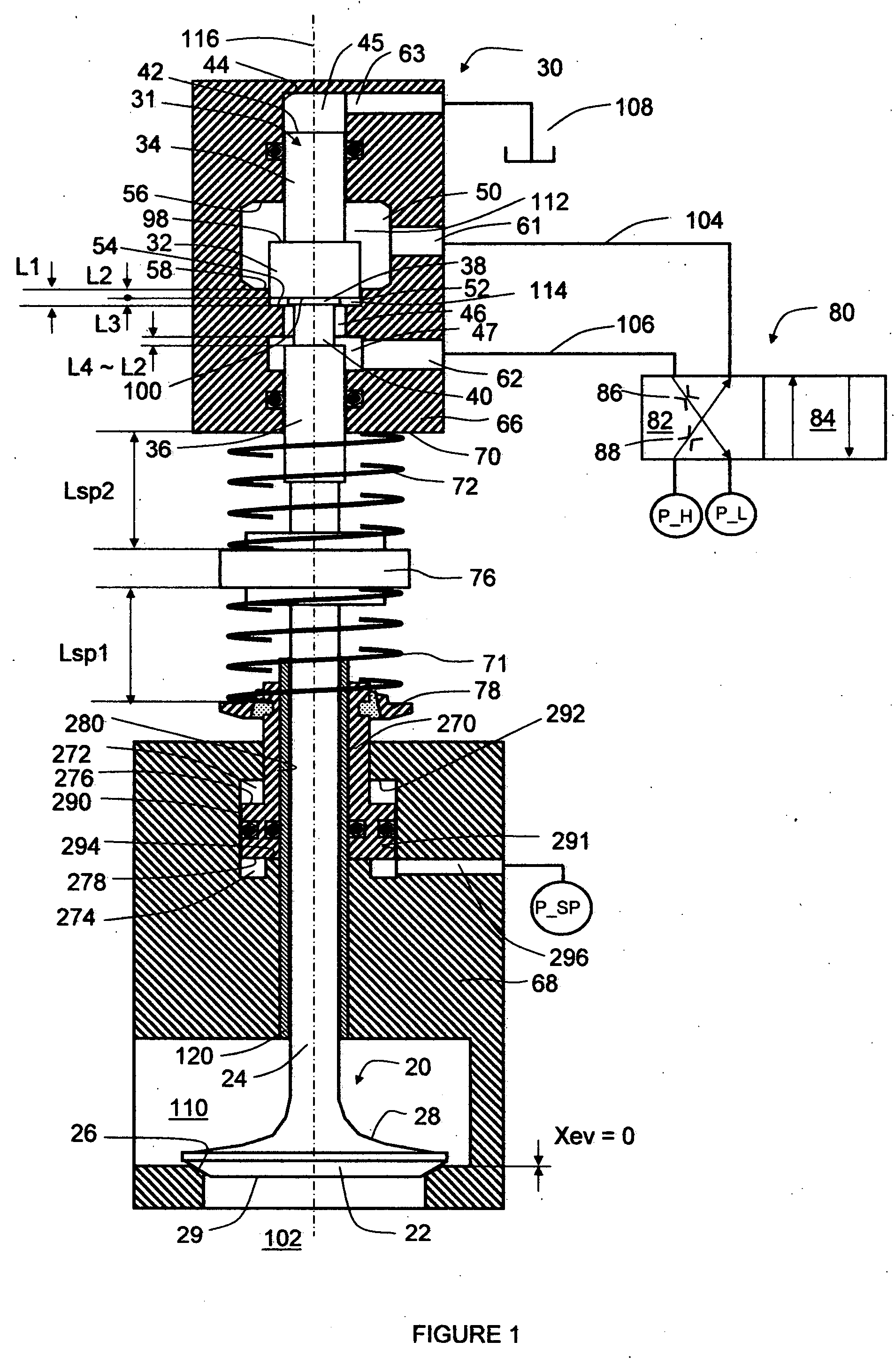
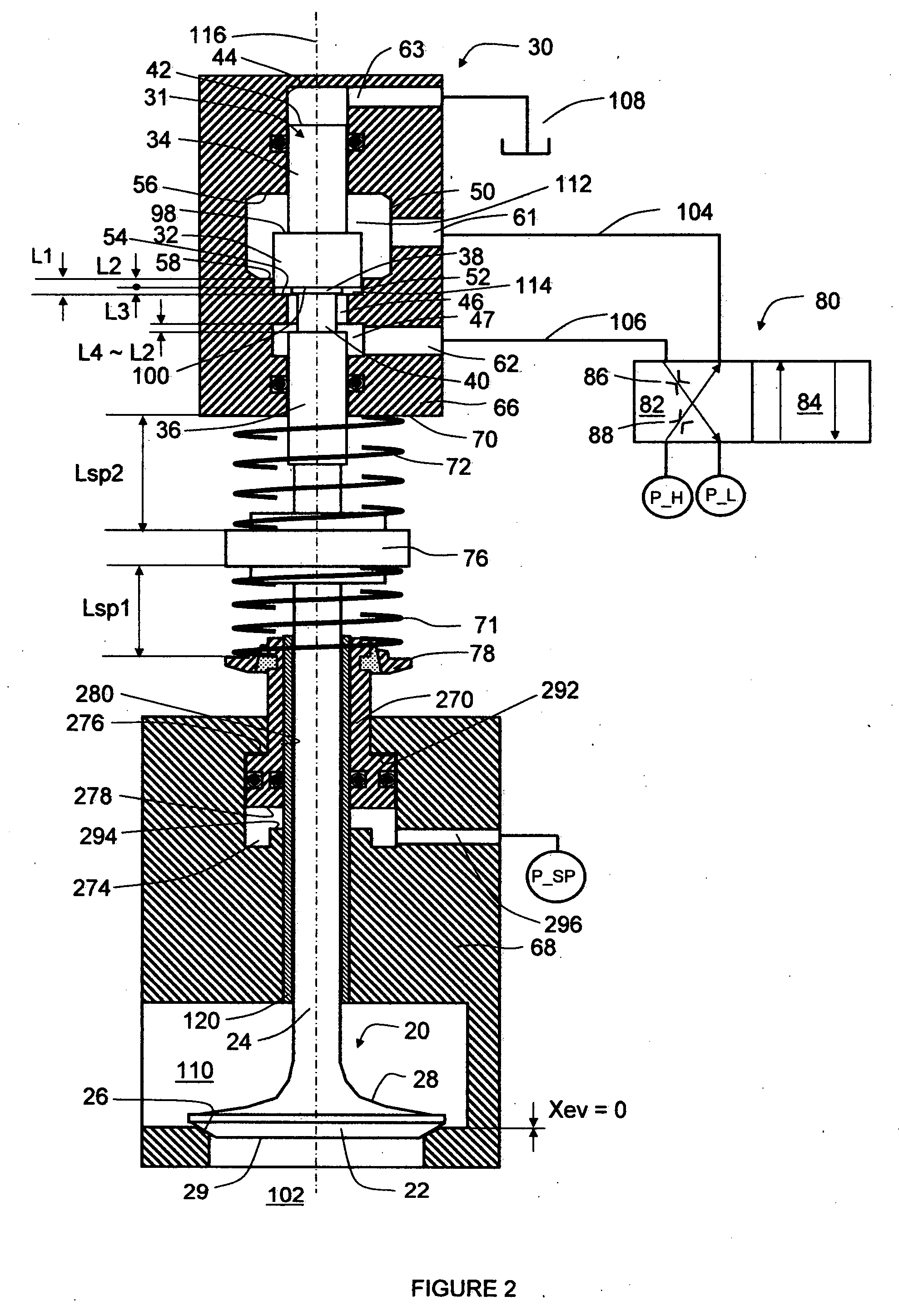
[0022]Referring now to FIG. 1, a preferred embodiment of the invention provides an engine valve control system using one piston, one or more bypass passages, and a set of centering spring means. The system comprises an engine valve 20, a fluid actuator 30, an actuation switch valve 80, a pair of actuation springs 71 and 72, and a spring control 270.

[0023]The actuation switch valve 80 supplies the fluid actuator 30 through a first port 61, a first-port passage 104, a second port 62, and a second-port passage 106. The first port 61 and the first-port passage 104 may be a physically or functionally continuous part, and so do the second port 62 and the second-port passage 106. The valve 80 is a 2-position 4-way valve. It has four ports connected with a low-pressure P_L fluid line, a high-pressure P_H fluid line, the first-port passage 104, and the second-port passage 106. It is switched either to a left position 82 and a right position 84. At the left position as shown in FIG. 1, the fi...


PUM


Abstract

Actuators and corresponding methods and systems for controlling such actuators offer efficient, fast, flexible control with large forces. In an exemplary embodiment, an fluid actuator includes a housing having first and second fluid ports, an actuation cylinder in the housing defining a longitudinal axis and having first and second ends in first and second directions, an actuation piston in the cylinder with first and second surfaces moveable along the longitudinal axis, a spring subsystem biasing the actuation piston to a neutral position, a first fluid space defined by the first end of the actuation cylinder and the first surface of the actuation piston, a second fluid space defined by the second end of the actuation cylinder and the second surface of the actuation piston; and a flow bypass that short-circuits the first and second fluid spaces when the actuation piston is not proximate to the second end of the actuation cylinder. A first flow mechanism controls fluid communication between the first fluid space and the first port, whereas a second flow mechanism controls fluid communication between the second fluid space and the second port. The first flow mechanism is always wide-open, whereas the second flow mechanism is open and closed when the flow bypass is closed and open, respectively. The system is able to latch the actuation piston at its second direction end position while making it possible for the actuation piston not to dwell at its first direction end position, thus reducing the overall actuation time.

Description

REFERENCE TO RELATED APPLICATION[0001]This application claims priority to Provisional U.S. Patent Application No. 60 / 809,117, file on May 26, 2006, the entire content of which are incorporated herein by reference.FIELD OF THE INVENTION[0002]This invention relates generally to actuators and corresponding methods and systems for controlling such actuators, and in particular, to actuators offering efficient, fast, flexible control with large forces.BACKGROUND OF THE INVENTION[0003]A split four-stroke cycle internal combustion engine is described in U.S. Pat. No. 6,543,225. It includes at least one power piston and a corresponding first or power cylinder, and at least one compression piston and a corresponding second or compression cylinder. The power piston reciprocates through a power stroke and an exhaust stroke of a four-stroke cycle, while the compression piston reciprocates through an intake stroke and a compression stroke. A pressure chamber or cross-over passage interconnects th...

Claims


Application Information

Patent Timeline
Patent Type & Authority Applications(United States)
IPC IPC(8): F01L1/34F01L9/02F01L9/10
CPCF01L9/02F01L2003/258F01L2001/34446F01L9/10
Inventor LOU, ZHENG
Owner LGD TECH LLC
Why Eureka
Try Eureka