Method and Control Unit for Operating an Internal Combustion Engine Having an Injection System

Inactive Publication Date: 2007-11-29
ROBERT BOSCH GMBH
View PDF7 Cites 4 Cited by
  • Summary
  • Abstract
  • Description
  • Claims
  • Application Information

AI Technical Summary

Benefits of technology

[0011] The precision with which the ascertained support points reflect the real response of a metering unit may be improved further in that, to begin with, they are specified only provisionally by the described method. It is then advisable to ascertain a multitude of provisional support points

Problems solved by technology

Inaccuracies may occur in the control of the pressure in the fue

Method used


Image

  • Method and Control Unit for Operating an Internal Combustion Engine Having an Injection System
  • Method and Control Unit for Operating an Internal Combustion Engine Having an Injection System
  • Method and Control Unit for Operating an Internal Combustion Engine Having an Injection System

Examples


Example

[0022] Hereinafter, example embodiments of the present invention are described in greater detail with reference to the appended Figures.

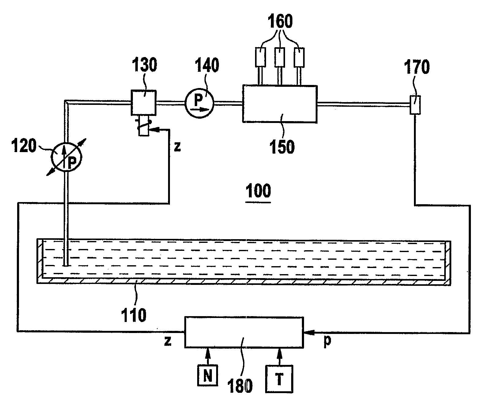
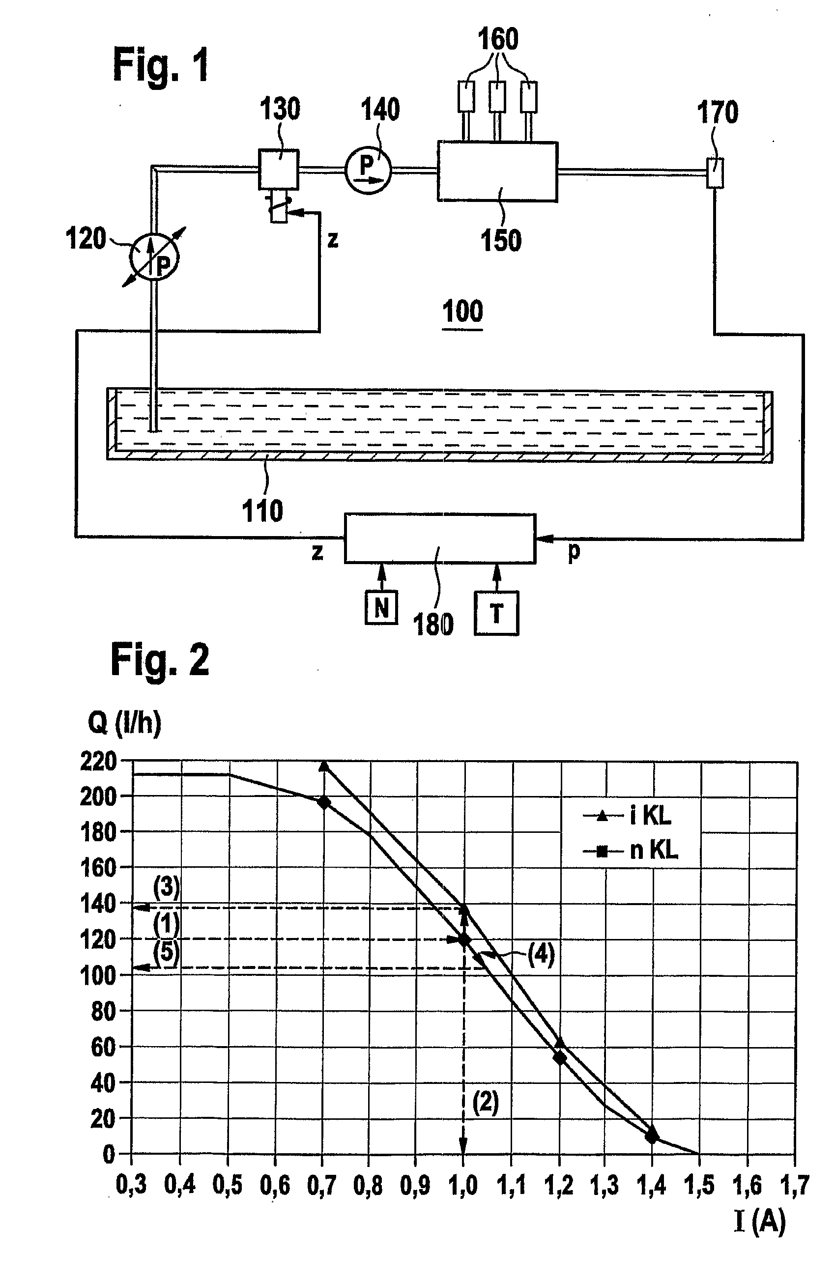
[0023]FIG. 1 illustrates an injection system 100 for an internal combustion engine. It includes a fuel tank 110 from which fuel is conveyed to a metering unit 130 with the aid of an electrical fuel pump 120. In response to a control signal z, metering unit 130 provides a specific fuel quantity for a downstream high-pressure pump 140. The high-pressure pump pumps the fuel into a fuel accumulator 150. The fuel is stored in fuel accumulator 150 under high pressure in order to be available to fuel injectors 160 of the internal combustion engine upon request. The magnitude of the pressure in the fuel accumulator is measured with the aid of a pressure sensor 170. Pressure sensor 170 conveys the measured pressure in fuel accumulator 150 in the form of a measuring signal p to a control unit 180 of injection system 100. Control unit 180 substantially functi...


PUM


Abstract

In a method, a computer program and a control unit for operating an internal combustion engine having an injection system, e.g., for a motor vehicle, in the injection system fuel is conveyed into a fuel accumulator by a metering unit and a high-pressure pump. The pressure in the fuel accumulator is recorded and controlled by control of the metering unit with the aid of the control unit. In order to consider also possible manufacturing tolerances of individual metering units in the control of the pressure in the fuel accumulator of such a system, which is already known as such, and thereby make the control more precise, an individual characteristic curve is provided for the actually used metering unit be ascertained and taken into account in the pressure regulation.

Description

FIELD OF THE INVENTION [0001] The present invention relates to a method, a computer program and a control unit for operating an internal combustion engine having an injection system, e.g., for a motor vehicle. Furthermore, the present invention relates to a data carrier having this computer program, and an internal combustion engine having this control unit. BACKGROUND INFORMATION [0002] Such a method and control unit are described, for example, in German Publication Patent Application No. 101 31 507, which describes an injection system for an internal combustion engine in which fuel is conveyed into a fuel accumulator by a metering unit and a high-pressure pump. The injection system also includes two closed-loop control circuits to regulate the pressure in the fuel accumulator. A first closed-loop control circuit regulates this pressure by suitable control of a pressure-control valve on the high-pressure side of the injection system. A second closed-loop control circuit regulates t...

Claims


Application Information

Patent Timeline
IPC IPC(8): F02D41/00F02D41/14F02D41/24F02D41/38F02M59/36F02M59/48F02M63/02
CPCF02D41/2441F02D41/2464F02D41/3845F02M63/0225F02D2250/31F02M59/366F02M59/48F02D2200/0602F02D41/00F02D41/38F02M63/00
Inventor HOLL, ANDREASSOVA, RUSLAN
Owner ROBERT BOSCH GMBH
Why Eureka
Try Eureka