Irrigation system valve manifold vault

a technology of irrigation system and valve manifold, which is applied in the direction of valve housing, hose connection, water supply installation, etc., can solve the problems of insufficient protection of valve manifolds, valve manifold assemblies generally remain unsupported within the valve manifolds, and none of the rain bird boxes includes the structure for pre-mounting valve manifolds and/or valve manifold pipe assemblies

Inactive Publication Date: 2007-11-29
SCHUMACHER SCOTT
View PDF5 Cites 8 Cited by
  • Summary
  • Abstract
  • Description
  • Claims
  • Application Information

AI Technical Summary

Benefits of technology

[0014]Accordingly, it is a first and principal object of the present invention to provide a novel irrigation system valve manifold cover that encloses a valve assembly in an easily accessible vault.
[0015]Yet another object of the present invention is to provide an irrigation system valve manifold cover that protects irrigation system valves from water intrusion, insects, and migrating soils.
[0016]Still another object is to provide a valve manifold assembly base and vault combination that secures, stabilizes, and protects the valve assembly from movement and damage from impact.

Problems solved by technology

However, none of the Rain Bird boxes includes structure for pre-mounting a valve manifold and / or valve manifold pipe assembly, which must be constructed and installed independently and then fit into the box.
Most of the known valve boxes provide insufficient protection of the valve assembly from water intrusion, insects, migrating soils, and so on.
Additionally, the valve manifold assemblies generally remain unsupported within the enclosure, and special apparatus or connectors must therefore be installed on the valve box or other structure provided in order to secure, stabilize, and protect the assembly from movement and damage.

Method used


Image

  • Irrigation system valve manifold vault
  • Irrigation system valve manifold vault
  • Irrigation system valve manifold vault

Examples


Embodiment Construction

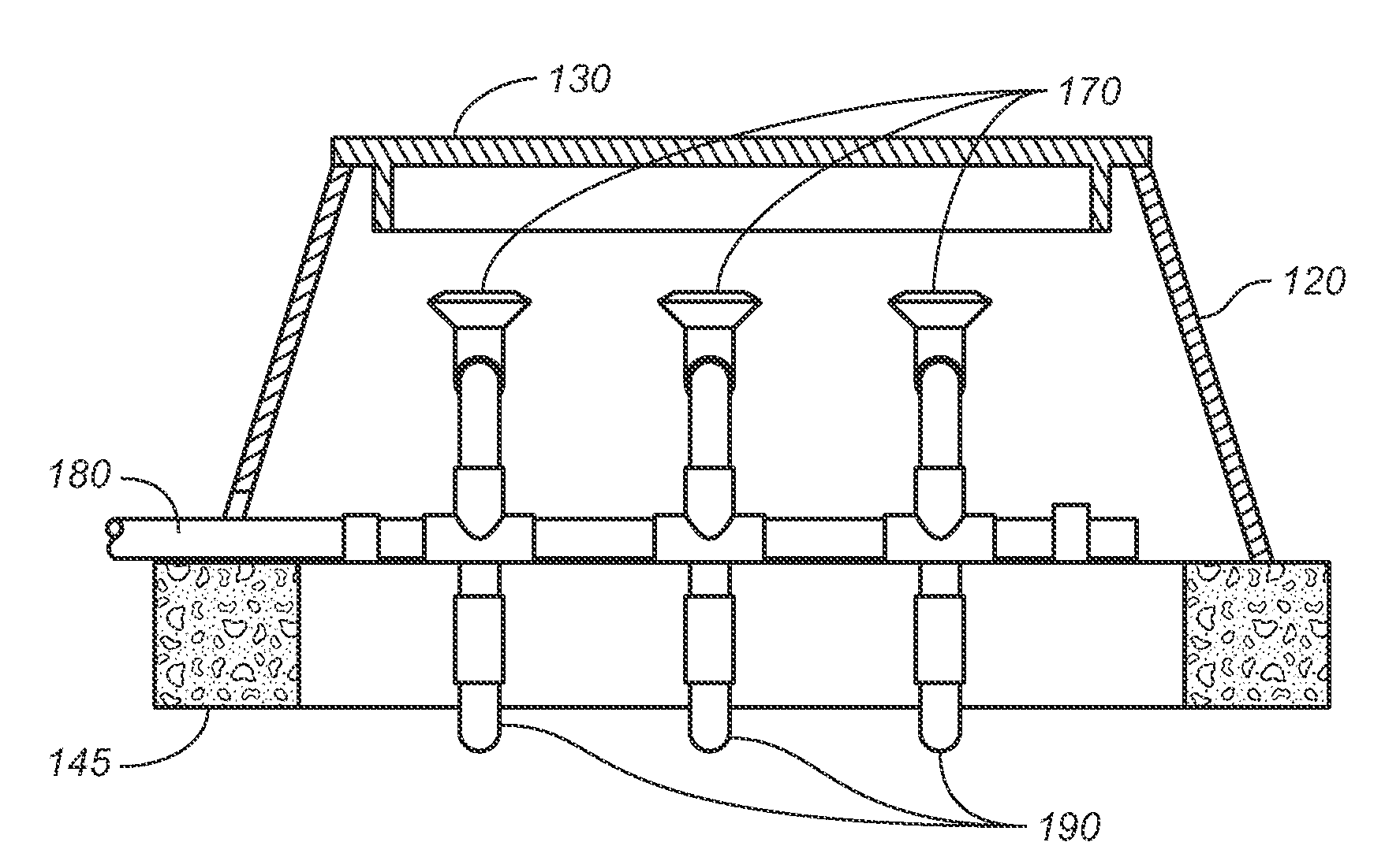
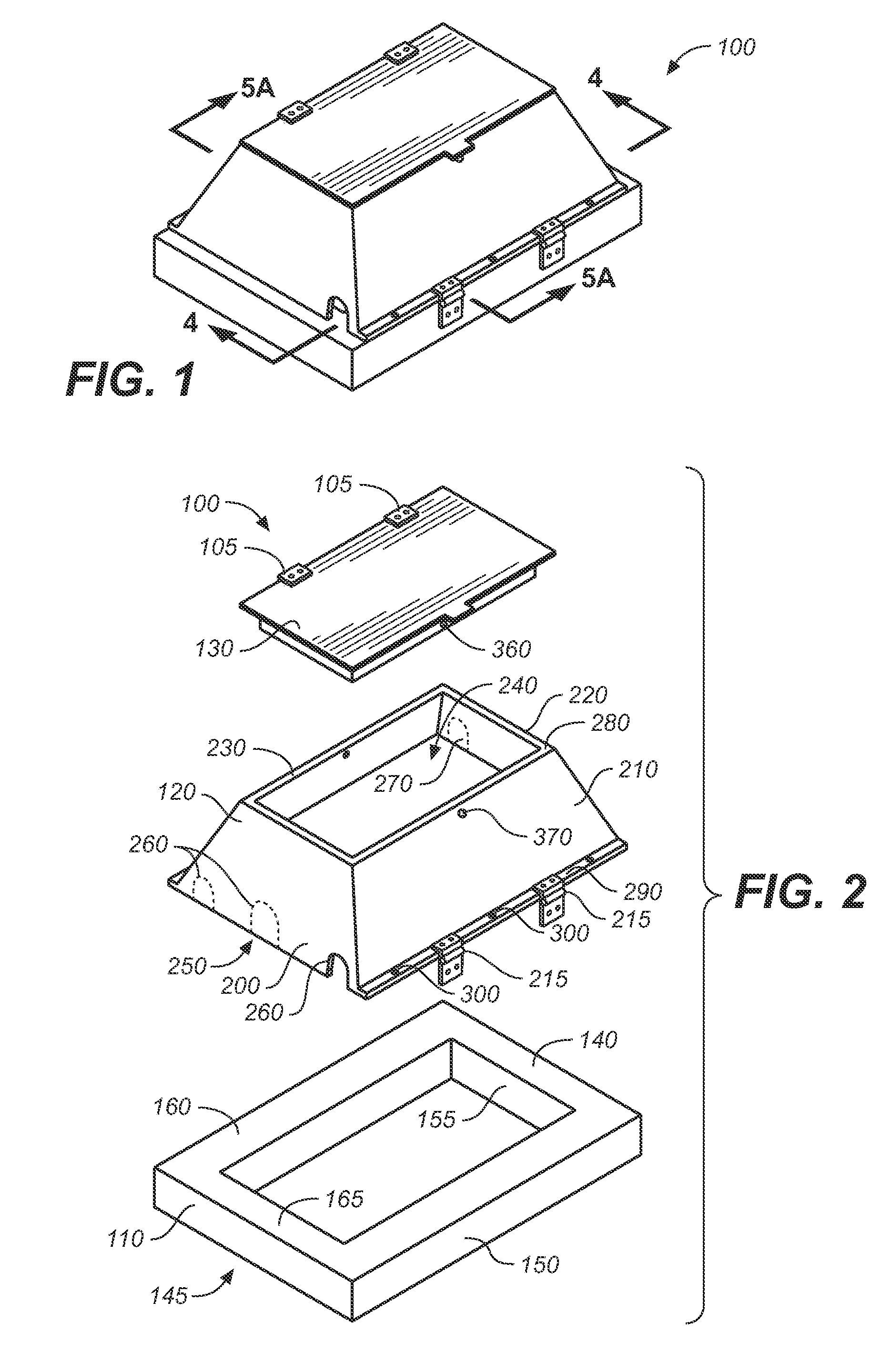
[0028]Referring to FIGS. 1 through 5B, wherein like reference numerals refer to like components in the various views, there is illustrated therein a new and improved irrigation system valve manifold vault, generally denominated 100 herein. These views, collectively, show that the inventive apparatus comprises three primary portions, including a support base 110, a vault enclosure 120, and a lid 130.

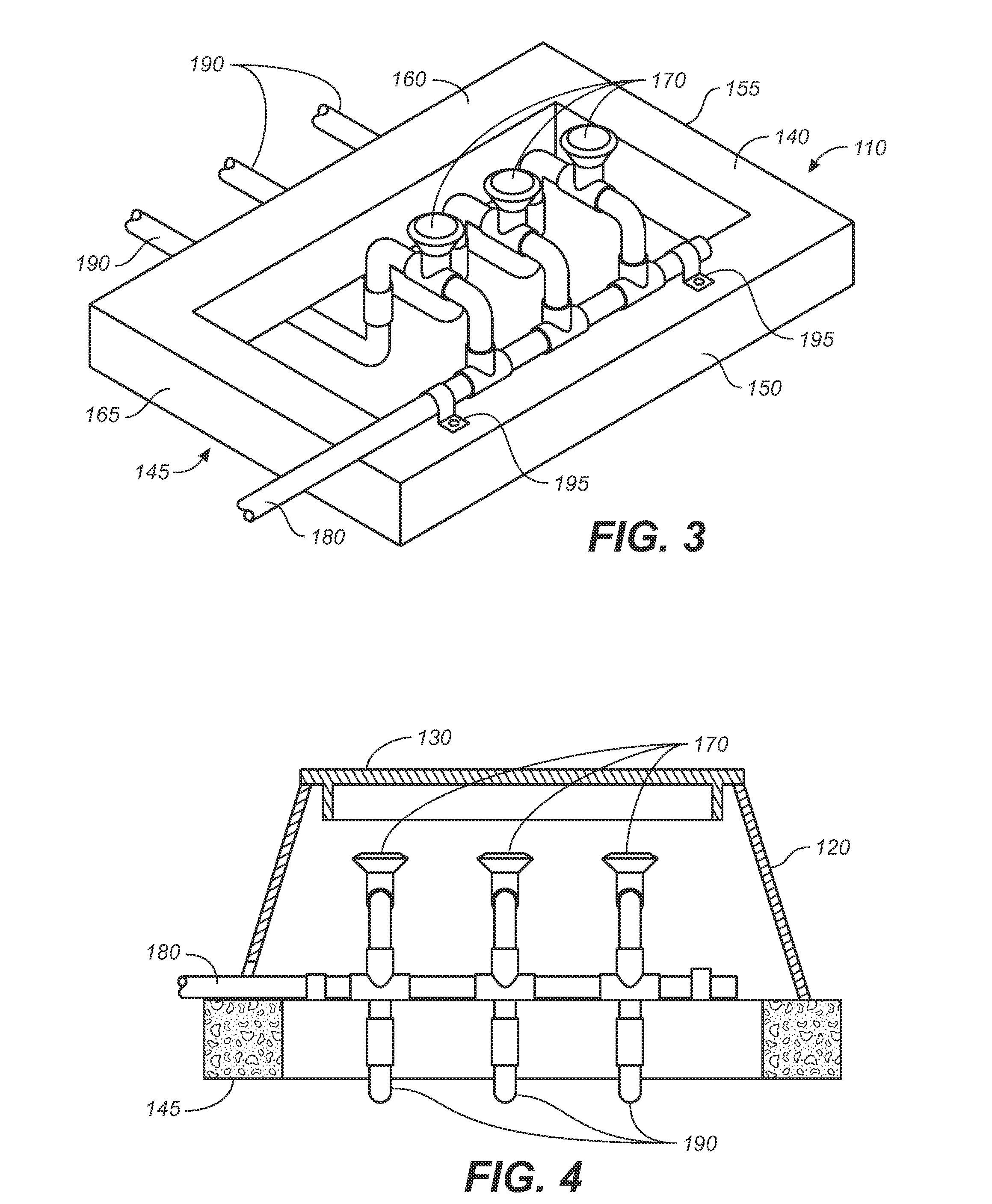
[0029]The support frame, or support base, 110 is generally configured in a solid rectangular frame conformation and has sufficient mass to support and secure valve manifolds of the kind typically installed in underground enclosures. It includes four frame members, including a front side 150, a right side 155, a back side 160, and a left side 165. The front, rear, right and left sides are joined to form a contiguous and substantially co-planar top side 140 and a contiguous and co-planar bottom side 145.

[0030]A plurality of valves 170 may then be configured into a valve manifold assembly wi...


PUM


Abstract

A valve manifold vault, lid, and vault support base for subsurface irrigation system valve manifolds. The vault, lid, and support base provide a secure enclosure that prevents movement of a valve assembly and protects valves and valve components.

Description

CROSS REFERENCE TO RELATED APPLICATIONS[0001]The present application claims the benefit of U.S. Provisional Patent Application Ser. No. 60 / 803,005, filed May 23, 2006.STATEMENT REGARDING FEDERALLY SPONSORED RESEARCH OR DEVELOPMENT[0002]Not applicable.REFERENCE TO A MICROFICHE APPENDIX[0003]Not applicable.TECHNICAL FIELD[0004]The present invention relates generally to irrigation system apparatus, and more particularly to irrigation system valve manifolds, and still more particularly to an irrigation system valve manifold enclosure for subsurface installation and protection of an electronically powered irrigation system valve manifold.BACKGROUND INFORMATION AND DISCUSSION OF RELATED ART[0005]Discussion of Related Art including information disclosed under 37 CFR §§1.97, 1.98: Irrigation system pipes are customarily buried below ground in order to protect the pipes from mechanical and weather related damage, to clear space for the free movement of foot and vehicular traffic, and elimina...

Claims


Application Information

Patent Timeline
Patent Type & Authority Applications(United States)
IPC IPC(8): F16K27/08
CPCF16K35/10F16K27/12Y10T137/7062
Inventor SCHUMACHER, SCOTT
Owner SCHUMACHER SCOTT
Why Eureka
Try Eureka