
Hand held bar code reader with improved image capture

Active Publication Date: 2007-11-29
SYMBOL TECH LLC
View PDF8 Cites 25 Cited by
  • Summary
  • Abstract
  • Description
  • Claims
  • Application Information

AI Technical Summary

Benefits of technology

[0005] An imaging-based bar code reader that includes an imaging and decoding system. When used on a stand to image documents, typically neither the stand or document is moving. Therefore blurring due to motion is not a problem. A sensor detects when the scanner is mounted to a stand. When commanded to take an image the scanner electronics and software modifies an auto-exposure process to minimize gain and lengthen exposure. This modification results in a scanner that is effective for scanning bar codes and yet also takes excellent pictures when mounted to a stand.
[0006] An imaging-based reader in one exemplary embodiment includes an imaging and decoding system for imaging a target image and if present decoding a target bar code. The imaging and decoding system has focusing optics and a sensor array. The focusing optics defines a field of view and focuses reflected illumination from an image onto the sensor array. A sensor determines if the reader is stationary with respect to the target and if it is, the imaging and decoding system responds to the sensor by adjusting the exposure period to reduce image distortion or noise.

Problems solved by technology

This high gain introduces noise and aberrations noticeable to the eye in the image.
This is acceptable for a barcode decoder, but degrades the image when using the device as a camera.

Method used


Image

  • Hand held bar code reader with improved image capture
  • Hand held bar code reader with improved image capture
  • Hand held bar code reader with improved image capture

Examples


Embodiment Construction

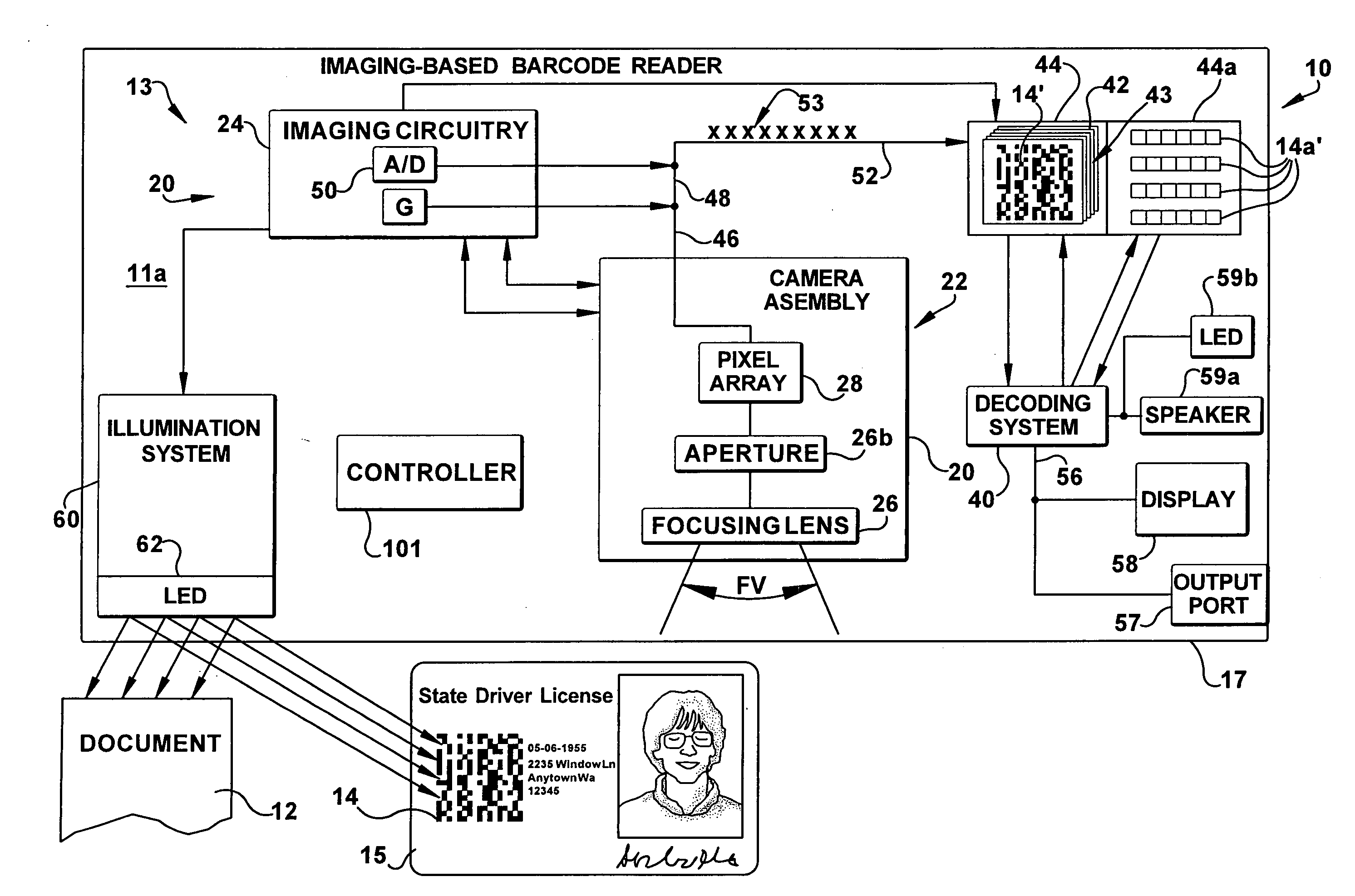
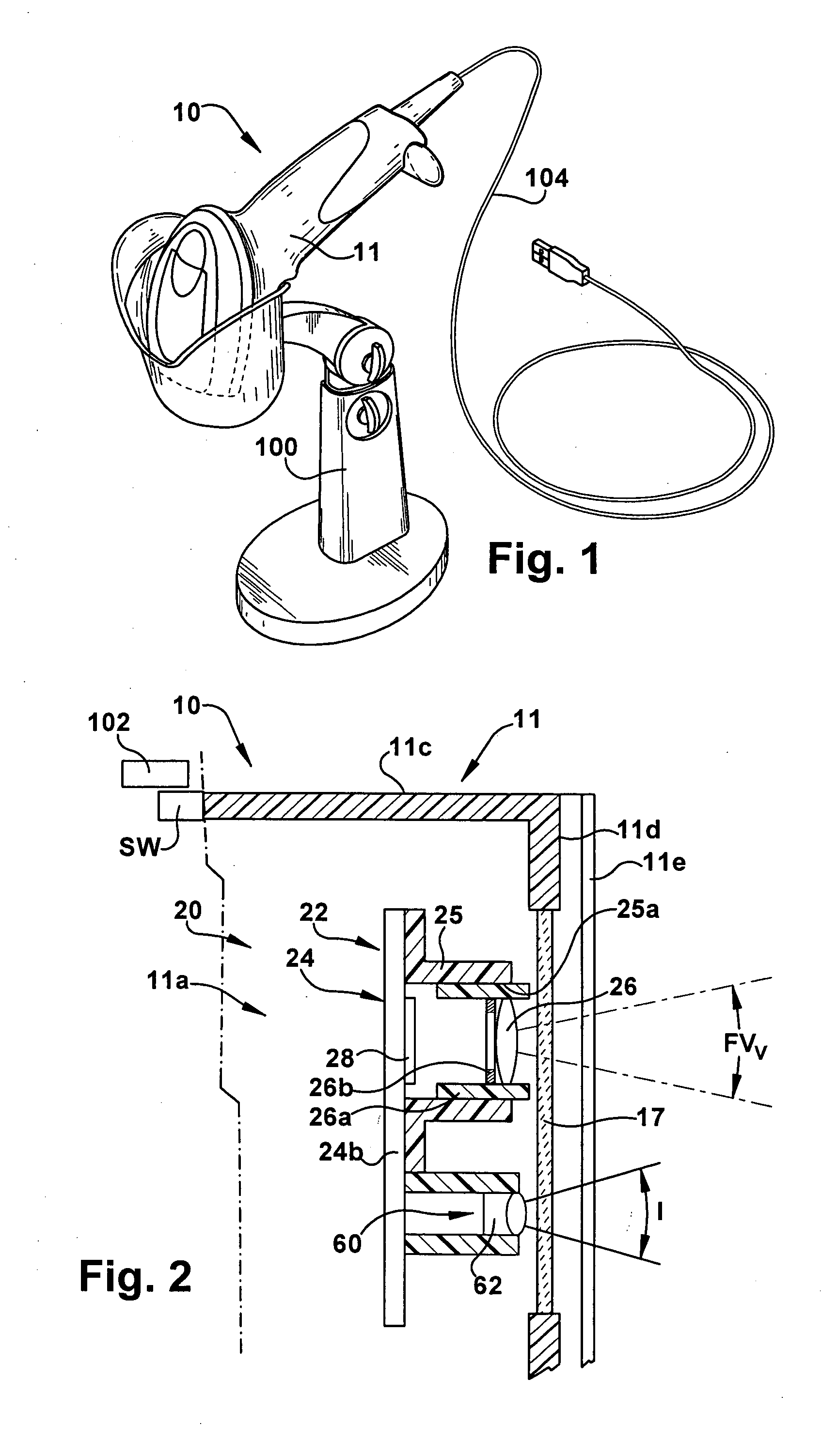
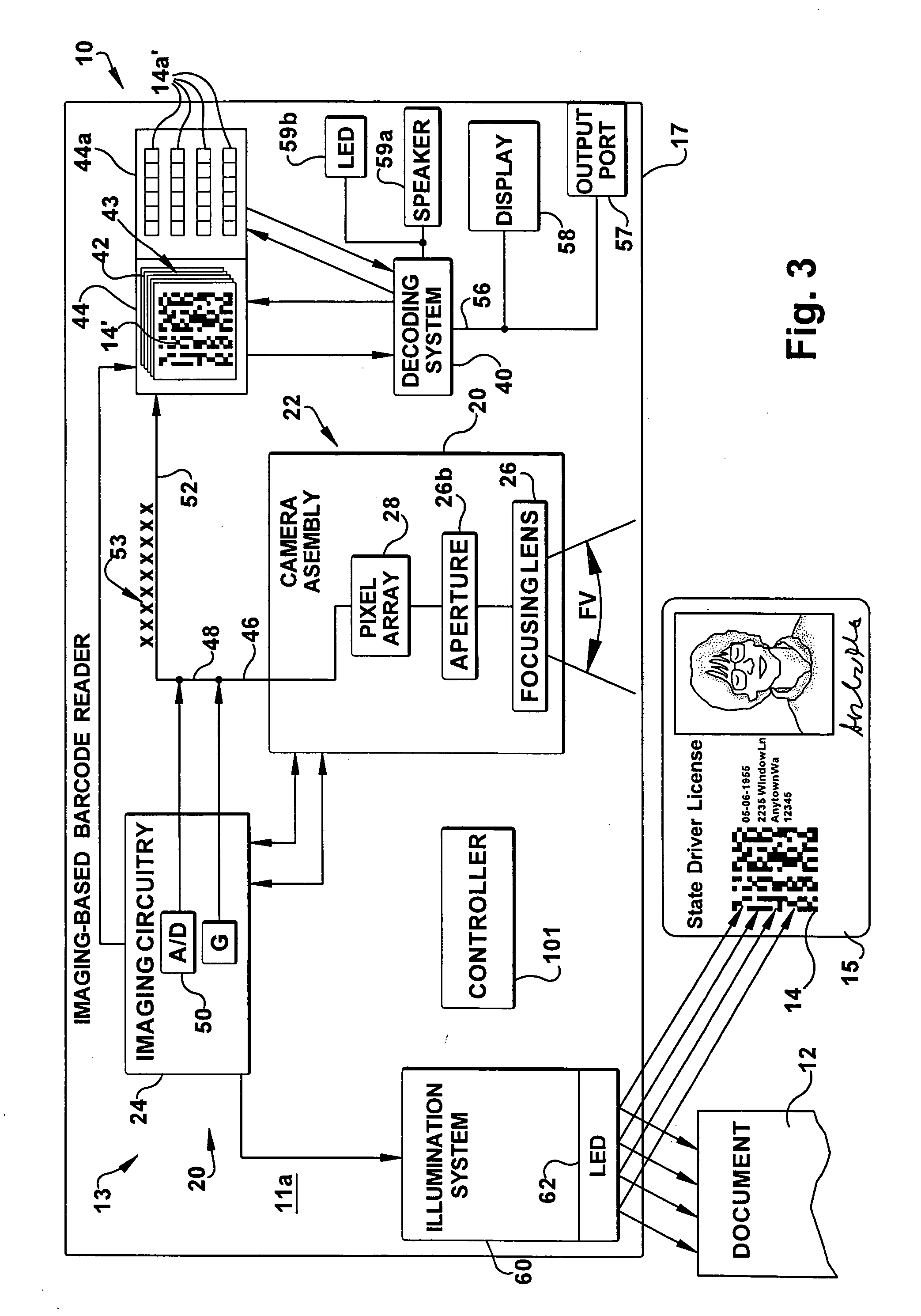
[0013] An imaging-based scanner that is capable of reading bar codes is shown schematically at 10 in the Figures. The scanner 10 is capable of imaging and decoding bar codes, such as a 2D bar code shown at 14 in FIG. 2. Additionally, the reader 10 is also capable of capturing images such as an image or a document 12 in FIG. 2 that contains signatures, graphics or the like. The bar code reader 10 includes a housing 11 supporting an imaging system 20 and a decoding system 40 (FIG. 3). The housing 11 supports a transparent window 17 through which reflected illumination from the target bar code 14 is received by the imaging system 20.

[0014] When enabled, the imaging system 20 captures an image frame 42 of a field of view FV of the imaging system. If imaging a target bar code 14, the imaging process captures a series of image frames 43 (FIG. 2) as the target bar code 14 moves through the imaging system field of view FV. Each of the series of captured image frames 43 includes at least a ...


PUM


Abstract

An imaging-based bar code reader that includes an imaging and decoding system. When used on a stand to image documents, typically neither the stand or document is moving. Therefore blurring due to motion is not an issue. A sensor detects when the scanner is mounted to a stand. When commanded to take an image the scanner electronics and software modifies an auto-exposure process to minimize gain and lengthen exposure. This modification results in the scanner that is effective for scanning bar codes and yet also takes excellent pictures when mounted to a stand.

Description

FIELD OF THE INVENTION [0001] The present invention relates to an imaging-based bar code reader and, more particularly, to a bar code reader that facilitates capturing images. BACKGROUND OF THE INVENTION [0002] Various electro-optical systems have been developed for reading optical indicia, such as bar codes. A bar code is a coded pattern of graphical indicia comprised of a series of bars and spaces having differing light reflecting characteristics. The pattern of the bars and spaces encode information. In certain bar codes, there is a single row of bars and spaces, typically of varying widths. Such bar codes are referred to as one dimensional (1D) bar codes. Other bar codes include multiple rows of bars and spaces, each row typically having the same width. Such bar codes are referred to as two dimensional (2D) bar codes and examples include PDF417 and DataMatrix bar code formats. By virtue of the use of multiple rows of features (bars and spaces), 2D bar codes typically allow more ...

Claims


Application Information

Patent Timeline
IPC IPC(8): G06K7/10
CPCG06K7/109G06K7/10722
Inventor BROCK, CHRISTOPHERLACKEMANN, THOMAS E.PANG, ROBERT JAMES
Owner SYMBOL TECH LLC
Learn More