
Vertical cavity surface emitting laser

a laser and vertical cavity technology, applied in semiconductor lasers, laser details, electrical devices, etc., can solve the problem of not easy to obtain high output of fundamental transverse modes, and achieve the effect of lowering the reflectance, and reducing the gain of high-order transverse modes

Active Publication Date: 2021-06-01
SONY CORP
View PDF42 Cites 0 Cited by
  • Summary
  • Abstract
  • Description
  • Claims
  • Application Information

AI Technical Summary

Benefits of technology

The patent describes a new design for a VCSEL, which allows for better control of the output of different optical modes. By creating high and low reflectance areas on the semiconductor layer, the invention reduces the gain of certain modes while maintaining the output of the fundamental mode. This results in a more efficient and stable laser with improved performance.

Problems solved by technology

Thus, there is a disadvantage that it is not easy to obtain high output of the fundamental transverse mode.

Method used


Image

  • Vertical cavity surface emitting laser
  • Vertical cavity surface emitting laser
  • Vertical cavity surface emitting laser

Examples


modified examples

[0077]In the foregoing embodiment, the laminated structure 23D is circular. However, for example, as illustrated in FIGS. 11A to 11C, the laminated structure 23D may be in the shape of a convex protruding toward a region sandwiched between the specific regions 23E. Otherwise, for example, as illustrated in FIGS. 12A to 12C, the laminated structure 23D may be in the shape having double convexes protruding toward two regions sandwiched between the specific regions 23E. Further, for example, as illustrated in FIGS. 13A to 13C, the laminated structure 23D may be in the shape of a cross in the region other than the region corresponding to each peak P of the opposed region opposing to the current injection region 15B.

[0078]For example, if the laminated structure 23D is circular, and the laminated structure 23D is arranged so that the center point C2 of the laminated structure 23D corresponds to the opposed region C1, as illustrated in FIG. 14, output of a simple transverse mode is able to...


PUM

PropertyMeasurementUnit
reflectanceaaaaaaaaaa
refractive index n2aaaaaaaaaa

Abstract

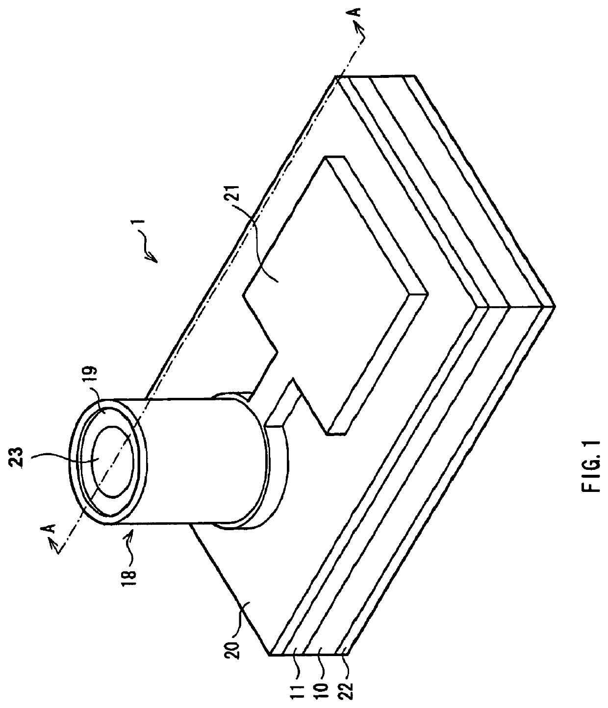
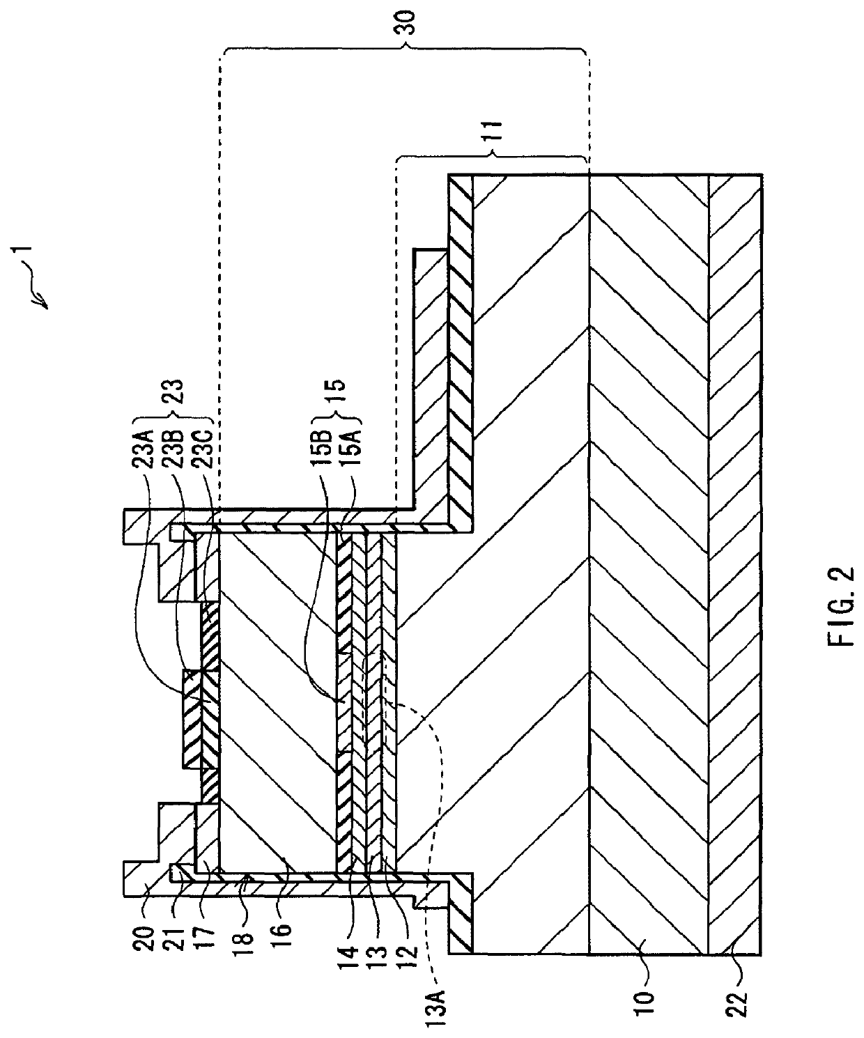
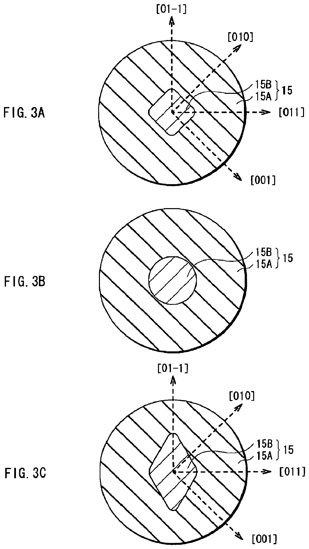
A Vertical Cavity Surface Emitting Laser (VCSEL) capable of providing high output of fundamental transverse mode while preventing oscillation of high-order transverse mode is provided. The VCSEL includes a semiconductor layer including an active layer and a current confinement layer, and a transverse mode adjustment section formed on the semiconductor layer. The current confinement layer has a current injection region and a current confinement region. The transverse mode adjustment section has a high reflectance area and a low reflectance area. The high reflectance area is formed in a region including a first opposed region opposing to a center point of the current injection region. A center point of the high reflectance area is arranged in a region different from the first opposed region. The low reflectance area is formed in a region where the high reflectance area is not formed, in an opposed region opposing to the current injection region.

Description

CROSS REFERENCES TO RELATED APPLICATIONS[0001]The present invention contains subject matter related to Japanese Patent Application JP 2008-002822 filed in the Japanese Patent Office on Jan. 10, 2008, and Japanese Patent Application JP 2008-305349 filed in the Japanese Patent Office on Nov. 28, 2008, the entire contents of which being incorporated herein by references.This application is a reissue of U.S. patent application Ser. No. 12 / 318,421, filed on Dec. 29, 2008, issued on Dec. 13, 2011, now U.S. Pat. No. 8,077,752, which claims priority to Japanese Patent Application No. 2008-002822, filed on Jan. 10, 2008 in the Japanese Patent Office, and claims priority to Japanese Patent Application No. 2008-305349, filed on Nov. 28, 2008 in the Japanese Patent Office, the entire contents of all of which are herein incorporated by reference. BACKGROUND OF THE INVENTION[0002]1. Field of the Invention[0003]The present invention relates to a Vertical Cavity Surface Emitting Laser (VCSEL) that ...

Claims


Application Information

Patent Timeline
Patent Type & Authority Patents(United States)
IPC IPC(8): H01S5/00H01S5/183H01S5/042
CPCH01S5/18391H01S5/18394H01S5/04254H01S5/18311H01S5/18327H01S5/18347H01S5/18358H01S2301/166H01S2301/176H01S2301/18
Inventor MAEDA, OSAMUSHIOZAKI, MASAKIARAKIDA, TAKAHIRO
Owner SONY CORP
Learn More