Evaporator assembly unit, especially for a vehicle heater or a reformer arrangement of a fuel cell system

a technology of assembly unit and fuel cell system, which is applied in the direction of heating type, combustion type, separation process, etc., can solve problems such as affecting the heat flow in the wall arrangement, and achieve the effect of improving the heat balance of the assembly uni

Inactive Publication Date: 2007-11-29
EBERSPAECHER CLIMATE CONTROL SYST GMBH & CO KG
View PDF12 Cites 8 Cited by
  • Summary
  • Abstract
  • Description
  • Claims
  • Application Information

AI Technical Summary

Benefits of technology

[0005]The object of the present invention is to design such an evaporator assembly unit such that the mixture formation process and the heat balance of the assembly unit are improved.
[0007]Consequently, the air introduced to form the mixture is introduced into the evaporator assembly unit according to the present invention not only via the air introduction shoulder provided at the bottom wall and extending into the evaporation chamber, but additionally via at least one opening provided in the area of the wall arrangement, i.e., the bottom wall and / or of the circumferential wall. This advantageously affects the flow within the evaporation chamber, especially in conjunction with the selection of the position and the shape of such an additional opening, and leads to a more uniform and better mixing of the fuel vapor with the air introduced and reduces the risk of formation of deposits when such an evaporation chamber is also used for the combustion operation. Furthermore, such an opening in the wall arrangement represents an interruption, which greatly affects the heat flow in the wall arrangement, which is made, in general, of a metallic material. It becomes possible in this manner to more strongly uncouple thermally areas of the wall arrangement, which are to be protected from excessive heating, from more intensely heated areas.
[0011]To improve the thermal uncoupling while providing at the same time the at least one second air introduction opening, it is proposed that the circumferential wall comprise two wall components, which follow each other in the direction of the longitudinal axis of the wall and are rigidly connected to one another, and that the auxiliary air opening arrangement comprise at least one second air introduction opening formed by an intermediate space between the wall components.
[0015]Furthermore, it is possible that at least one second air introduction opening is elongated (e.g., in a circumferential direction). In particular, the provision of elongated air introduction openings for the auxiliary air opening arrangement leads to a very strong thermal uncoupling of different areas of the wall arrangement with a comparatively large opening cross section.
[0017]Especially if the auxiliary air opening arrangement comprises at least one second air introduction opening in the circumferential wall, it is advantageous if the air introduction arrangement is designed, furthermore, for introducing air in the direction of the circumferential wall of the wall arrangement.

Problems solved by technology

Furthermore, such an opening in the wall arrangement represents an interruption, which greatly affects the heat flow in the wall arrangement, which is made, in general, of a metallic material.

Method used


Image

  • Evaporator assembly unit, especially for a vehicle heater or a reformer arrangement of a fuel cell system
  • Evaporator assembly unit, especially for a vehicle heater or a reformer arrangement of a fuel cell system
  • Evaporator assembly unit, especially for a vehicle heater or a reformer arrangement of a fuel cell system

Examples


Embodiment Construction

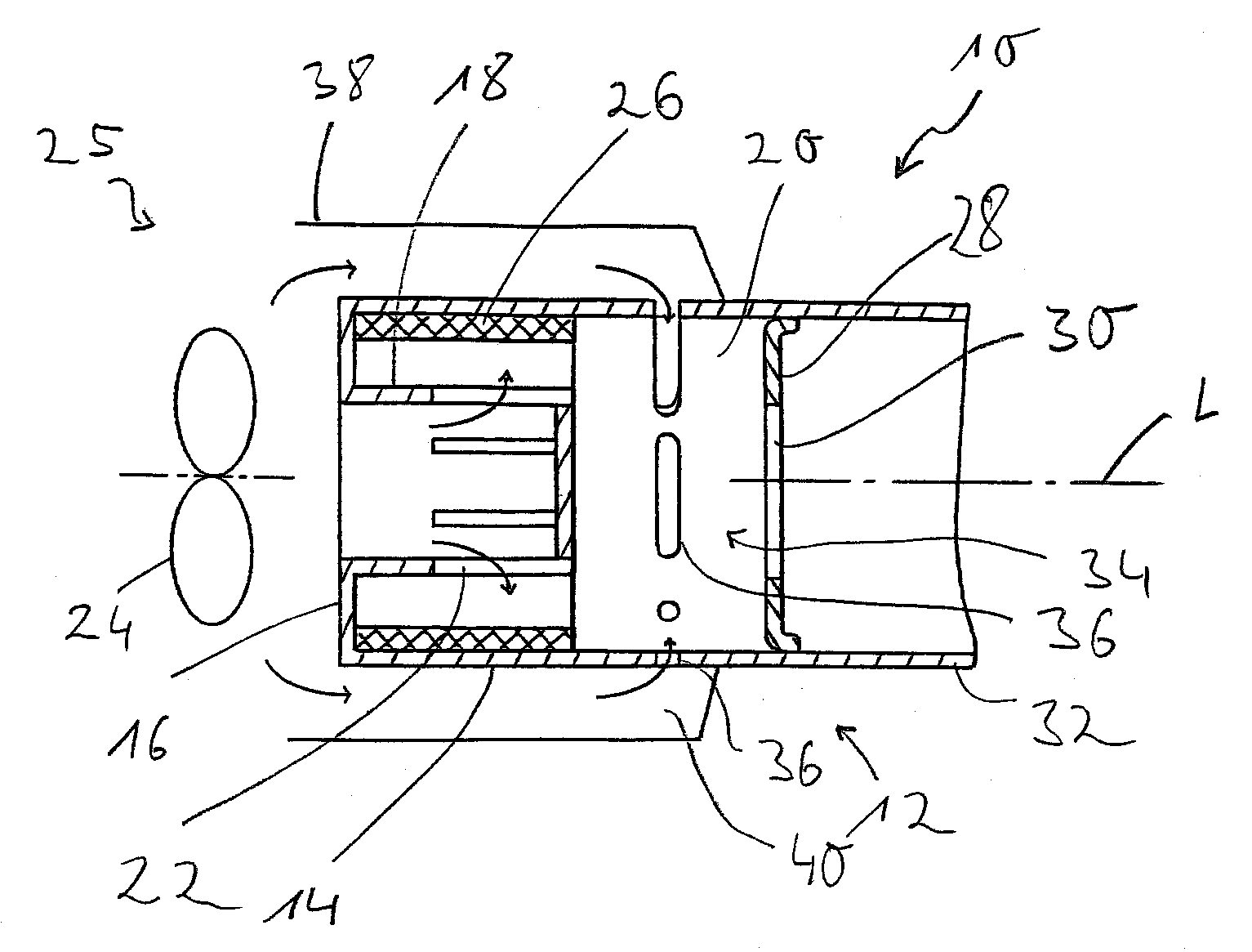
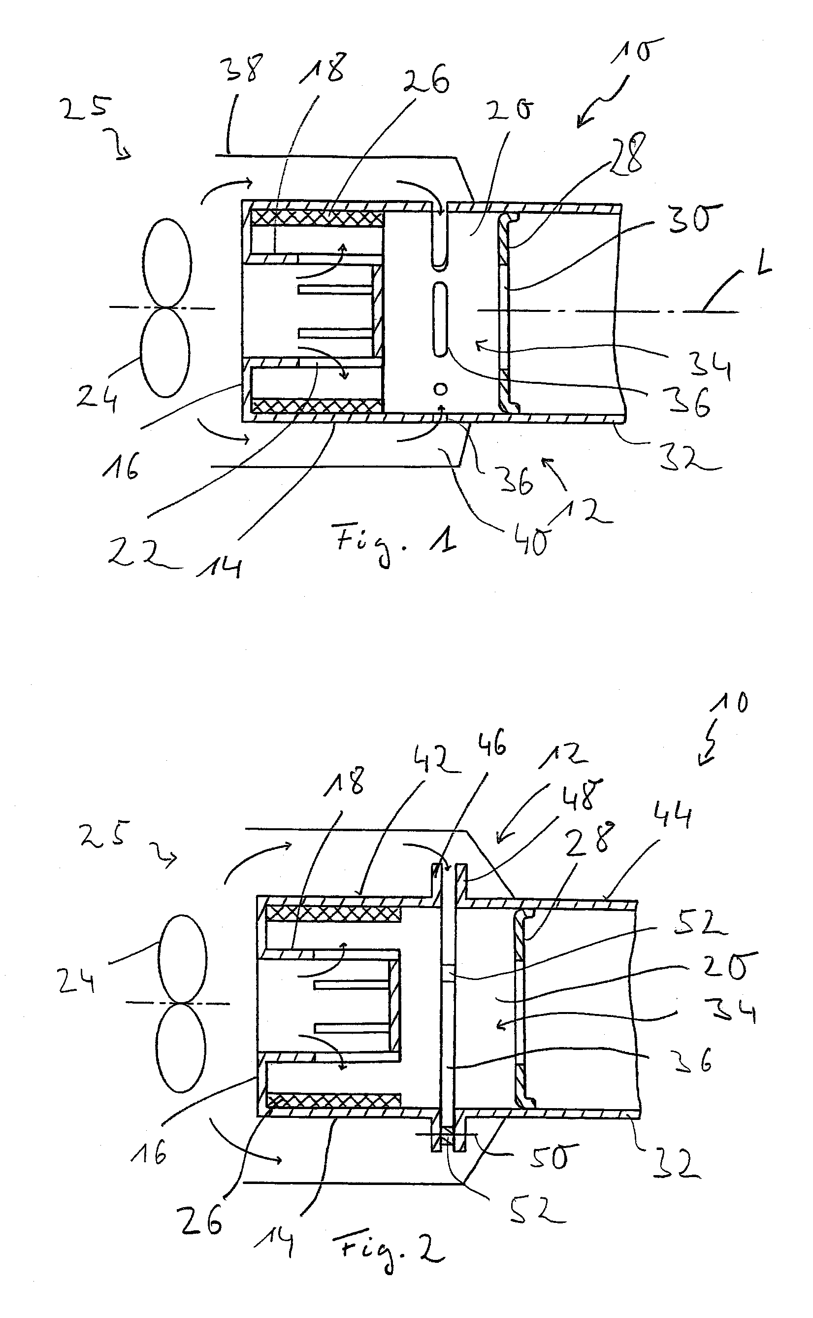
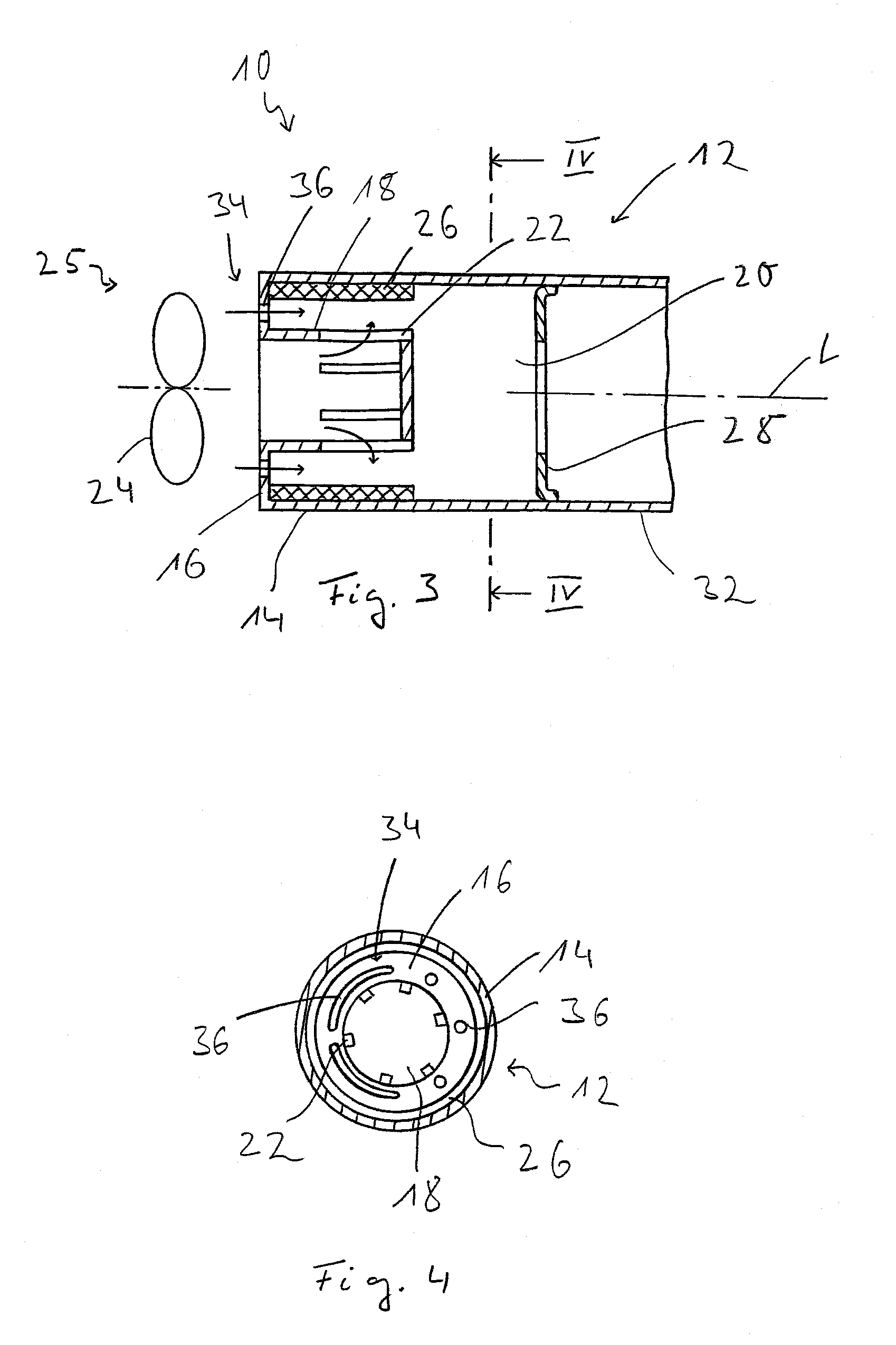
[0024]Referring to the drawings in particular, An evaporator assembly unit is generally designated by 10 in FIG. 1. This evaporator assembly unit 10, which can be inserted, for example, into an evaporative burner of a vehicle heater, in which the heat generated by combustion is transferred to a heat carrier medium, comprises a wall arrangement generally designated by 12 with a circumferential wall 14 and with a bottom wall 16. The circumferential wall 14 and the bottom wall 16 of the wall arrangement 12 form a pot-like assembly unit elongated in the direction of a longitudinal axis L of the wall. The circumferential wall 14 and the bottom wall 16 are designed in the example being shown as integral components of the wall arrangement 12, which can be manufactured, for example, by a casting process from metallic material. The circumferential wall 14 and the bottom wall 16 could, of course, also be made available as separate components and assembled subsequently.

[0025]An air introductio...


PUM

PropertyMeasurementUnit
areaaaaaaaaaaa
circumferential areasaaaaaaaaaa
forceaaaaaaaaaa

Abstract

An evaporator assembly unit, especially for a vehicle heater or a reformer arrangement of a fuel cell system, includes a wall arrangement (12) enclosing an evaporation chamber (20) with a circumferential wall (14) and with a bottom wall (16). An air introduction shoulder (18) extending in the direction of a wall longitudinal axis (L) is provided with a plurality of first air introduction openings (22). Evaporator medium (26), that is porous at least in some areas, is provided on the side of the wall arrangement (12) facing the evaporation chamber (20). An auxiliary air opening arrangement (34) with at least one second air introduction opening (36) is provided in the wall arrangement (12).

Description

CROSS REFERENCE TO RELATED APPLICATIONS[0001]This application claims the benefit of priority under 35 U.S.C. §119 of German Patent Application DE 10 2006 024 221.1 filed May 23, 2006, the entire contents of which are incorporated herein by reference.FIELD OF THE INVENTION[0002]The present invention pertains to an evaporator assembly unit, especially for a vehicle heater or a reformer arrangement of a fuel cell system, comprising a wall arrangement enclosing an evaporation chamber with a circumferential wall and a bottom wall, wherein an air introduction shoulder extending in the direction of a wall longitudinal axis with a plurality of first air introduction openings is provided at the bottom wall and wherein an evaporator medium that is porous at least in some areas is provided on the side of the wall arrangement facing the evaporation chamber.BACKGROUND OF THE INVENTION[0003]Such evaporator assembly units are used, for example, for evaporative burners in vehicle heaters. The liqui...

Claims


Application Information

Patent Timeline
Patent Type & Authority Applications(United States)
IPC IPC(8): B01D47/00C10J1/10
CPCF23C2900/99009F23D3/22F23L1/00F23D11/404F23D11/445F23D3/40F23D2900/21002F23L9/00Y10S261/65Y10S261/83
Inventor SCHMIDT, OLIVER
Owner EBERSPAECHER CLIMATE CONTROL SYST GMBH & CO KG
Why Eureka
Try Eureka