Brushless motor

a brushless motor and motor body technology, applied in the direction of windings, dynamo-electric components, cooling/ventilation arrangements, etc., can solve the problems of insufficient cooling effect, inability to directly remove heat generated by the coils, and decrease in the output torque of the motor, so as to improve the cooling efficiency of the motor and the coils. , the effect of reducing the stagnation of hea

Inactive Publication Date: 2007-11-29
MABUCHI MOTOR
View PDF6 Cites 116 Cited by
  • Summary
  • Abstract
  • Description
  • Claims
  • Application Information

AI Technical Summary

Benefits of technology

[0013]According to the present invention, a flow of cooling air generated within the motor casing due to rotation of the cooling fan or the like easily passes through the core slot spaces, whereby the motor-coil cooling efficiency can be improved. Further, even in the case where forced cooling by mans of a cooling fan or the like is not performed, a flow of air is improved, and st

Problems solved by technology

If the generated heat is not removed, the current decreases because of an increase in the resistance of the coils, with a resultant decrease in output torque of the motor.
Therefore, heat generated from the coils cannot be directly removed, and therefore a sufficient cooling effect cannot be attained.
However, in ether case, the wiring hinders cooling of the motor.
Therefore, the length and size of the motor increase, and due to complexity of the wire connection, the numbers of steps and components increase

Method used


Image

  • Brushless motor
  • Brushless motor
  • Brushless motor

Examples


first embodiment

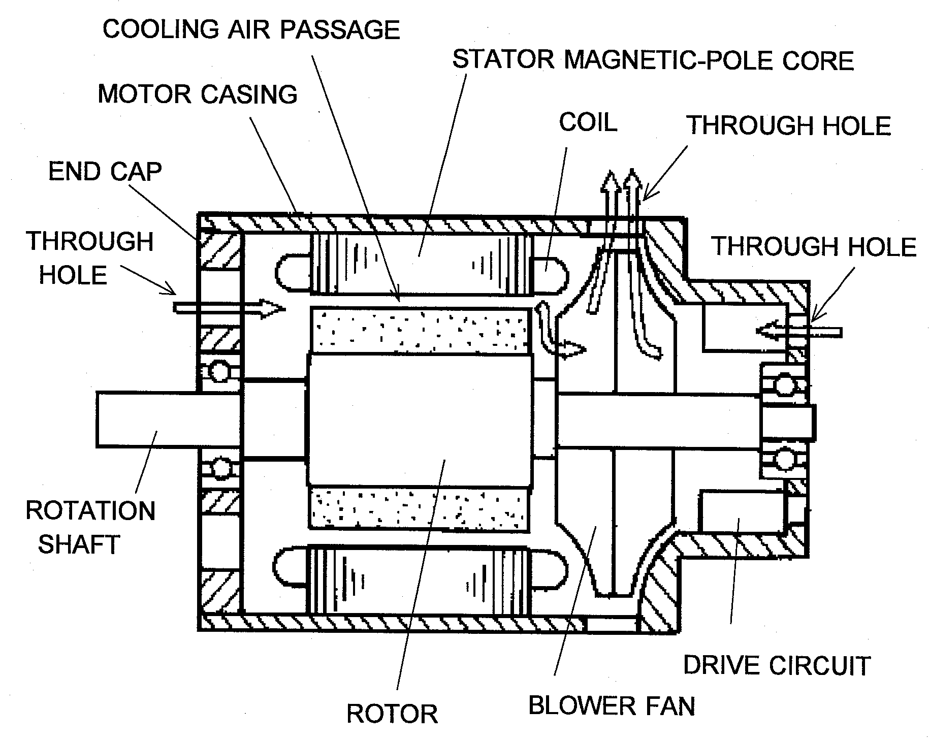
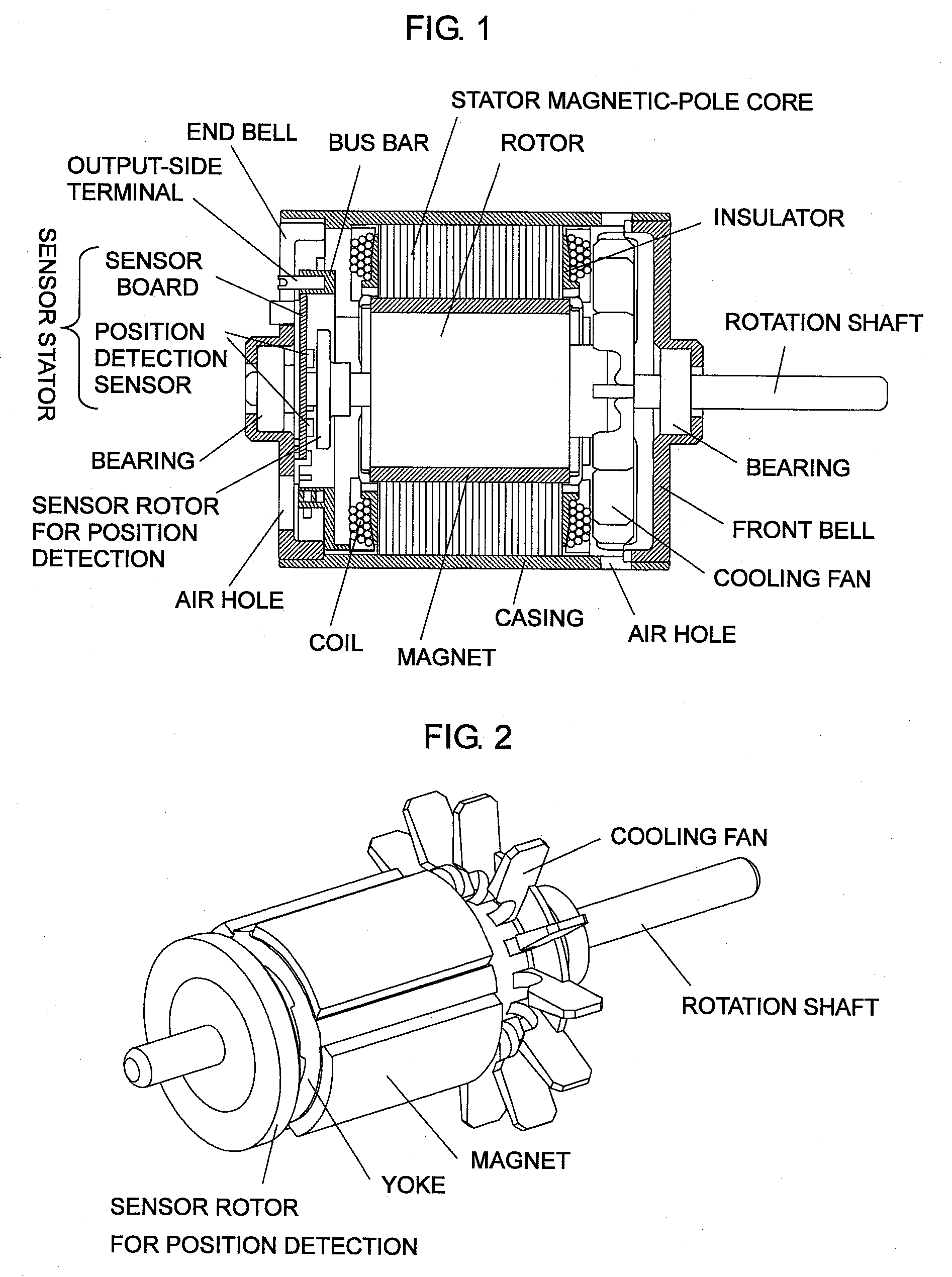
[0034]The present invention will now be described by way of examples. FIG. 1 is a cross sectional view showing the overall structure of a brushless motor equipped with a bus bar according to a A motor housing is composed of a cylindrical casing formed of a metal or a resin, a front bell formed of a metal or a resin and attached to one end opening portion of the cylindrical casing, and an end bell formed of a metal or a resin and attached to the other end opening portion of the cylindrical casing. A stator is fixed to the inner wall surface of the cylindrical casing. The stator includes a magnetic-pole core, and coils wound around the core via an insulating means such as an insulator. Bearings for supporting a rotation shaft of a rotor are fixedly accommodated in central portions of the front bell and the end bell. One end of the shaft projects from the front bell toward the outside of the motor housing, and an external apparatus to be driven is connected to the projecting end.

[0035...

second embodiment

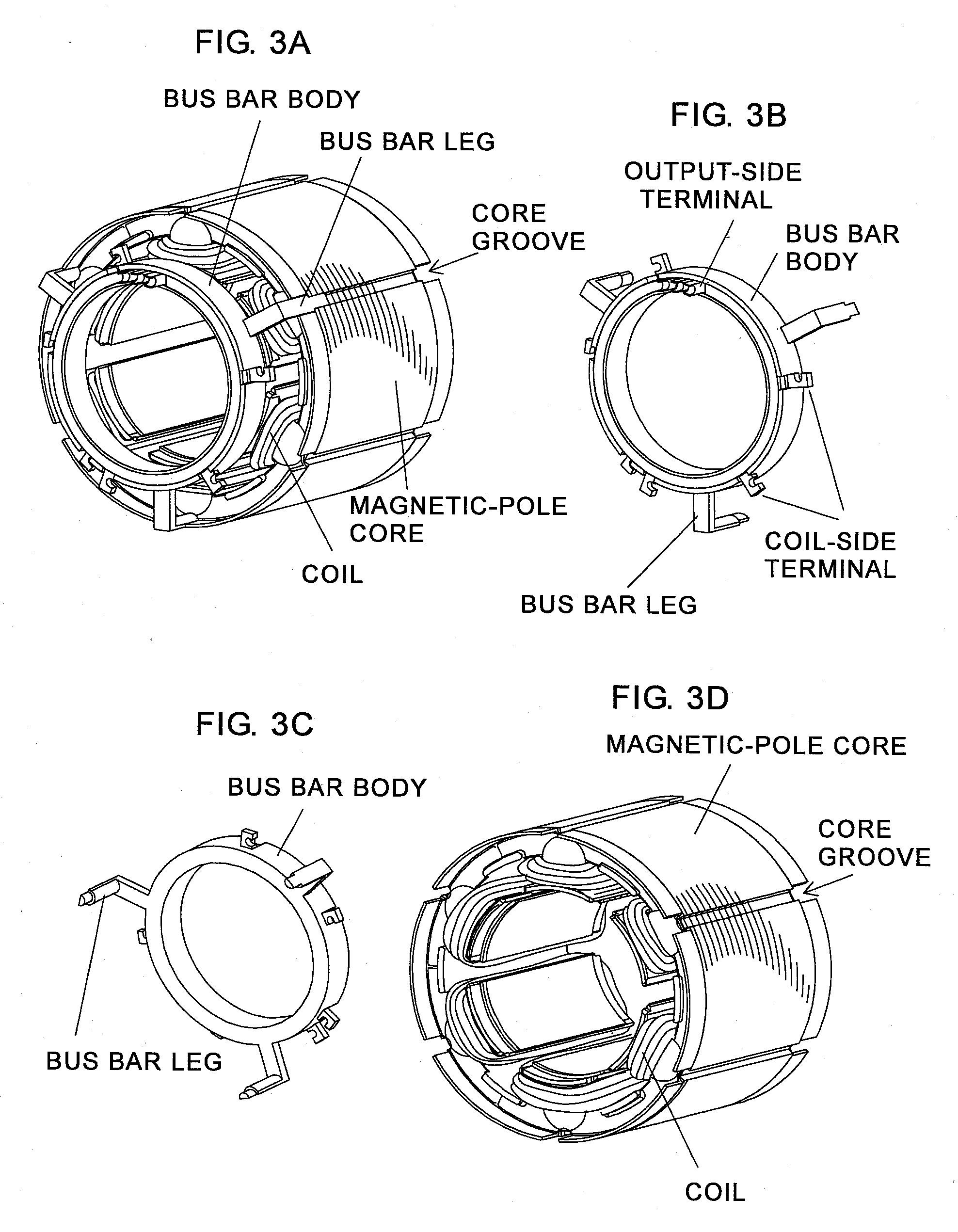
[0045]As shown in FIGS. 9A and 9B, the bus bar also includes a cylindrical bus bar body formed of a resin, and three or more (three in the in the illustrated example) bus bar legs integrally formed with the bus bar body. The legs are inserted into and attached to the axially extending core grooves which are provided on the outer circumferential surface of the magnetic-pole core, and, as shown in FIG. 1, the stator with the bus bar attached thereto are fixedly disposed within the cylindrical casing.

[0046]As in the case of the bus bar according to the first embodiment, the bus bar body has a small radial dimension or length such that the bus bar body does not close the inter-coil clearances. However, the second embodiment differs from the first embodiment in that a cooling air follow passage is secured on the radially inner side of the bus bar body. The occupying area can be reduced by means of disposing the wiring bars of the bus bar to form two or more layers of wiring bars in the ...


PUM


Abstract

A plurality of coils wound around a stator magnetic-pole core are connected together and connected to output wires by use of a bus bar. The bus bar having a generally cylindrical body portion is disposed at one axial end of the stator magnetic-pole core, around which the coils are wound such that clearances are formed within magnetic-pole core slots, with an axial clearance formed between the bus bar and the coils. The body portion has such a radial dimension that at least a portion of the clearances within the magnetic-pole core slots is left uncovered. Air holes are formed in the motor housing on opposite sides of the stator magnetic-pole core to thereby form cooling air passages extending through the magnetic-pole core slots.

Description

BACKGROUND OF THE INVENTION[0001]1. Field of the Invention[0002]The present invention relates to a brushless motor in which stator coils are connected together and are connected to output wires by use of a bus bar.[0003]2. Description of the Related Art[0004]When a motor is used for drive of an electric power tool or the like, a relatively large current flows through the coils of the motor. Therefore, heat generated as a result of the current flowing through the coils must be removed by means of cooling. If the generated heat is not removed, the current decreases because of an increase in the resistance of the coils, with a resultant decrease in output torque of the motor. A conventional cooling apparatus for a motor has a structure as shown in FIG. 11 (see Japanese Patent No. 2882594). A plurality of radial and axial through holes are formed in a motor casing and an end cap, respectively. A stator, composed of a magnetic-pole core and coils wound around the magnetic-pole core, and ...

Claims


Application Information

Patent Timeline
IPC IPC(8): H02K9/00H02K9/06
CPCH02K3/50H02K9/06H02K5/20H02K3/522H02K5/207
Inventor KINOSHITA, NOBUOMATSUOKA, YOUICHIRO
Owner MABUCHI MOTOR
Why Eureka
Try Eureka