
Automatic input-gain control circuit and method thereof

an input-gain control and control circuit technology, applied in amplifiers, amplifiers with semiconductor devices/discharge tubes, amplifiers, etc., can solve the problems of time delay, stepped distortion, and difficulty in freely changing the level, so as to prevent or substantially reduce the distortion of output signals

Inactive Publication Date: 2007-11-29
SAMSUNG ELECTRONICS CO LTD
View PDF6 Cites 22 Cited by
  • Summary
  • Abstract
  • Description
  • Claims
  • Application Information

AI Technical Summary

Benefits of technology

[0013]Accordingly, it is an aspect of the present invention to prevent or substantially reduce distortion of the output signal by limiting the output level when an over-input occurs.
[0014]It is another aspect of the present invention to prevent or substantially reduce clipping of an output signal when an over-input occurs.
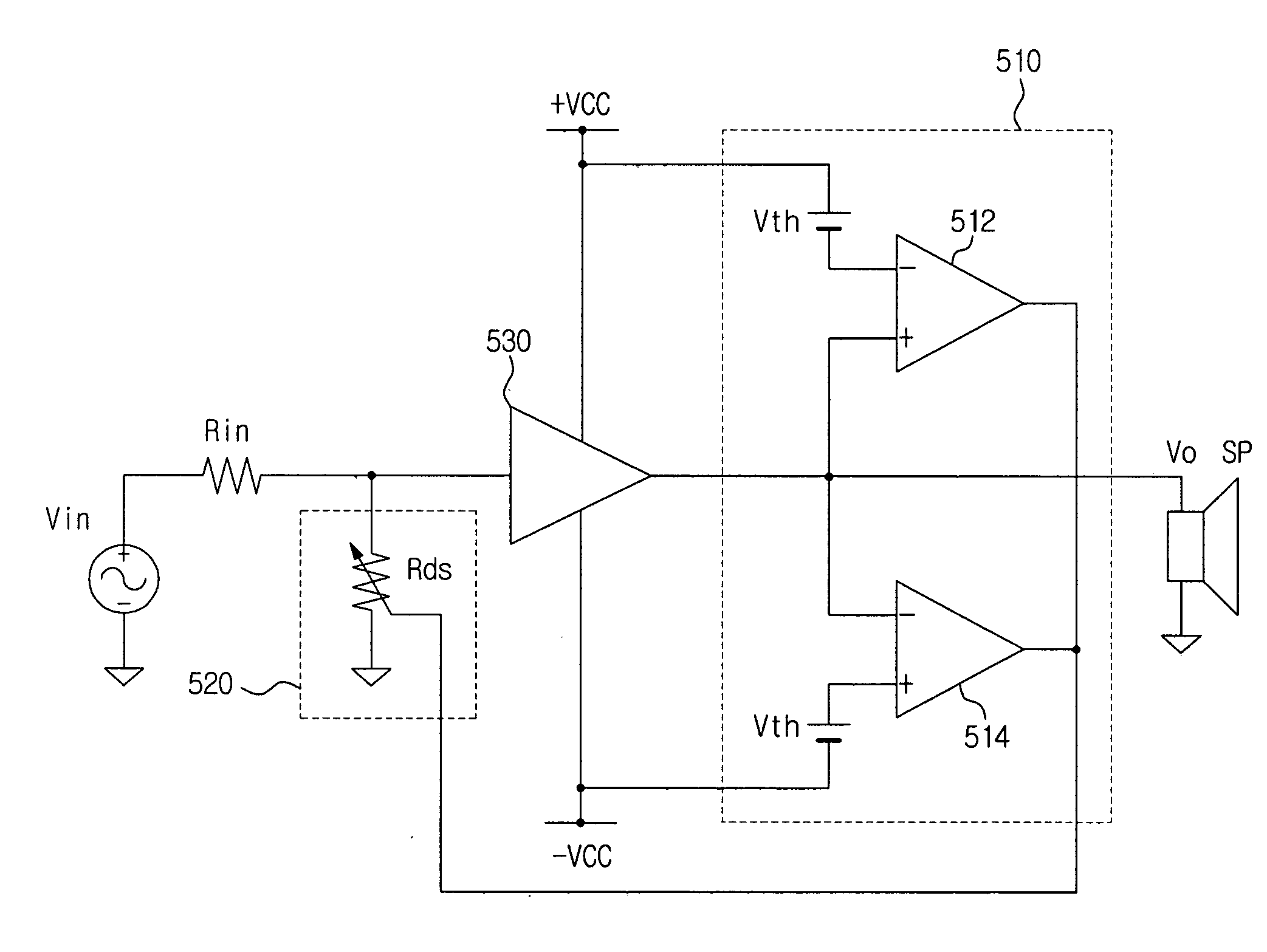
[0016]The forgoing aspects of the present invention can be accomplished by providing an automatic input-gain control circuit for automatically attenuating a gain of an acoustic signal based on a pre-set limited level to minimize a distortion of the acoustic signal caused by clipping of the acoustic signal and limit an over-input of the acoustic signal so as to input the acoustic signal within a dynamic range if the acoustic signal is not input within the dynamic range in an audio apparatus including an acoustic amplifier and a switching amplifier, and a method thereof.

Problems solved by technology

A time delay necessarily occurs due to a characteristic of the integrator.
Thus, a stepped distortion occurs.
Thus, it is difficult to freely vary the level.
As a result, it is difficult to accurately cope with variations in a gain of an amplifier or a power supply voltage.

Method used


Image

  • Automatic input-gain control circuit and method thereof
  • Automatic input-gain control circuit and method thereof
  • Automatic input-gain control circuit and method thereof

Examples


Embodiment Construction

[0042]The matters defined in the description such as a detailed construction and elements are provided to assist in a comprehensive understanding of the embodiments of the invention and are merely exemplary. Accordingly, those of ordinary skill in the art will recognize that various changes and modifications of the embodiments described herein can be made without departing from the scope and spirit of the invention. Also, descriptions of well-known functions and constructions are omitted for clarity and conciseness.

[0043]Hereinafter, exemplary embodiments of the present invention will be described in detail with reference to the accompanying drawings.

[0044]Certain embodiments of the present invention are characterized in that an over-input signal is attenuated to prevent a clipping distortion D1 caused by an over-input and an over-output and a stepped high frequency distortion D2 caused by a saturation of an internal block of the audio amplifier, so that an output signal does not ap...


PUM


Abstract

An automatic input-gain control circuit of an audio amplifier and a method thereof are provided. If an acoustic signal exceeds a dynamic range, a gain of the acoustic signal can be automatically attenuated based on a pre-set limit level to minimize a distortion of the acoustic signal caused by clipping of the acoustic signal and limit an over-input so as to input the acoustic signal within the dynamic range. Thus, an original form of an over-input signal on a specific level or more can be maintained but only a gain of the over-input signal can be attenuated. As a result, a distortion of an output waveform caused by clipping of the output waveform can be minimized, and a harmonic distortion and a stepped high frequency noise occurring during clipping can be simultaneously removed.

Description

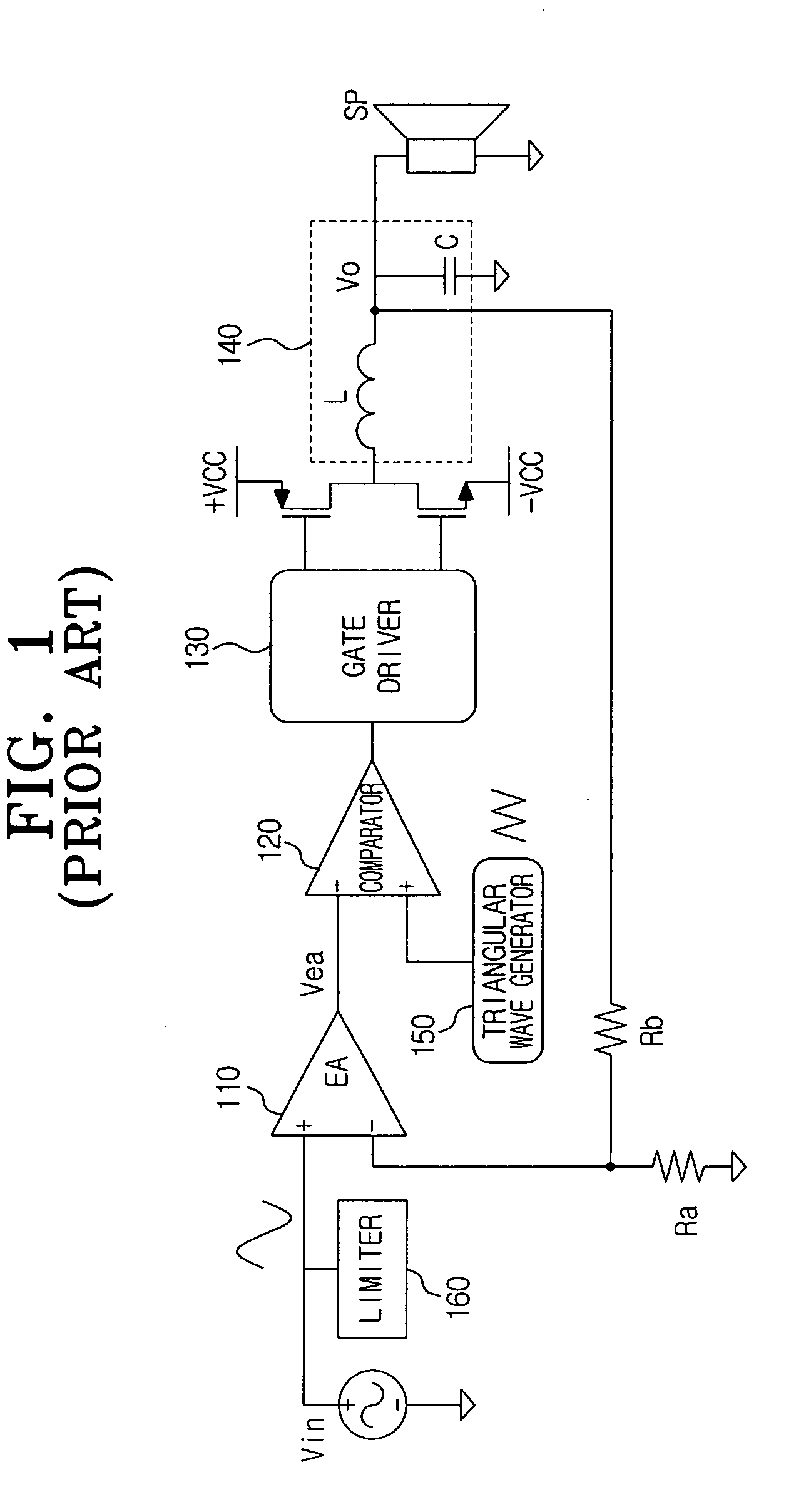
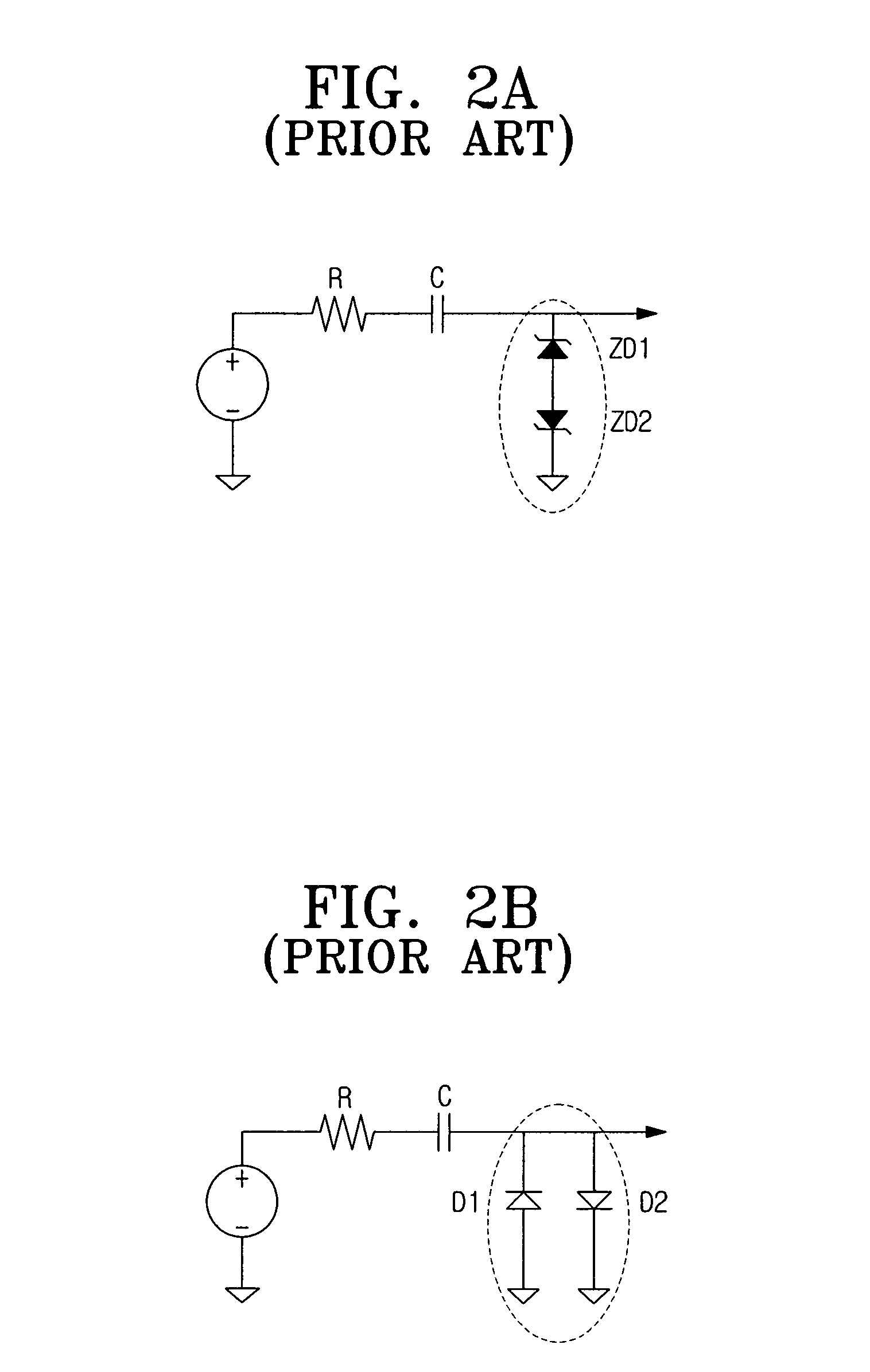
CROSS-REFERENCE TO RELATED APPLICATIONS[0001]This application claims the benefit under 35 U.S.C. § 119(a) of Korean Patent Application No. 2006-46281, filed on May 23, 2006, in the Korean Intellectual Property Office, the entire disclosure of which is hereby incorporated by reference.BACKGROUND OF THE INVENTION[0002]1. Field of the Invention[0003]The present invention relates to an automatic input-gain control circuit of an audio amplifier and a method thereof.[0004]2. Description of the Related Art[0005]In general, an analog-to-digital (A to D) D-class amplifier circuit performs pulse width modulation (PWM) on an acoustic signal to transform the acoustic signal into a type of digital signal, amplifies the digital signal, and passes the amplified digital signal through a low pass filter (LPF) to recover an original analog signal.[0006]FIG. 1 is a schematic diagram illustrating a structure of a conventional D-class amplifier circuit. Referring to FIG. 1, the conventional D-class ampl...

Claims


Application Information

Patent Timeline
IPC IPC(8): H03G3/20H03G3/00
CPCH03F3/2171H03G11/002H03G7/004H03F3/217H03G5/16
Inventor KIM, NAM-INKIM, YUN-YONGKIM, SUNG-WOO
Owner SAMSUNG ELECTRONICS CO LTD
Learn More