
Servo demodulating circuit and method

a technology of demodulating circuit and magnetic transfer medium, which is applied in the field of magnetic transfer medium demodulation circuit and method, can solve the problems of significant cost problems, longer time required for servo writing by stw, and difficulty in performing electron beam lithography on every disk

Inactive Publication Date: 2007-11-29
TOSHIBA STORAGE DEVICE CORP
View PDF7 Cites 15 Cited by
  • Summary
  • Abstract
  • Description
  • Claims
  • Application Information

AI Technical Summary

Benefits of technology

[0042]By employing the servo demodulating circuit or method relating to the present invention, it is possible to solve the problems of amplitude fluctuation of the replayed signal due to the above causes and demodulation error caused by the phase fluctuation.

Problems solved by technology

Since there has been a current trend of ever increasing track recording density in the magnetic disks, the time required for servo writing by STW has become longer, causing significant cost problems.
For commercial production of patterned media and discrete track media, due to production cost concerns and writing time length, it is difficult to perform electron beam lithography on every disk.
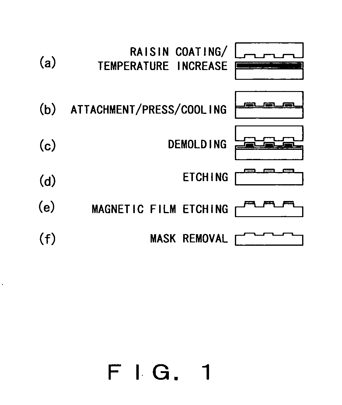
In the magnetic transfer method described in the above Non-Patent Document, however, the extent of attachment between the master disk and a slave medium (magnetic spacing) directly influences the intensity of magnetic attraction (measure of magnetization), and thus several nanometers (nm) of difference in the height of asperity on the master disk or minute surface roughness of the slave medium would cause fluctuation of the replayed signal amplitude, creating a problem involving insufficient signal quality.
There is a problem, however, such that in a case of a magnetically transferred signal, if the above amplitude fluctuation is present in a sector, all of the fluctuation will result in demodulation errors.
A further problem exists such that when performing, in the conventional method, the magnetic transfer to the perpendicular magnetic recording medium, magnetization is not likely to be even, causing a significant demodulation error.
The occurrence of such events causes a problem in which the edge positions are misaligned, resulting in phase fluctuation caused by amplitude fluctuation of the replayed signal.

Method used


Image

  • Servo demodulating circuit and method
  • Servo demodulating circuit and method
  • Servo demodulating circuit and method

Examples


Embodiment Construction

[0043]In the following description, although details of the embodiments of the present invention are set forth with reference to the drawings, it does not limit the present invention. It should be noted that the term “(magnetic recording) medium” in the description represents a perpendicular magnetic recording medium, a planar magnetic recording medium and other media known to a person skilled in the art unless otherwise provided.

[Overview of Servo Demodulating Apparatus Relating to Embodiments of Present Invention]

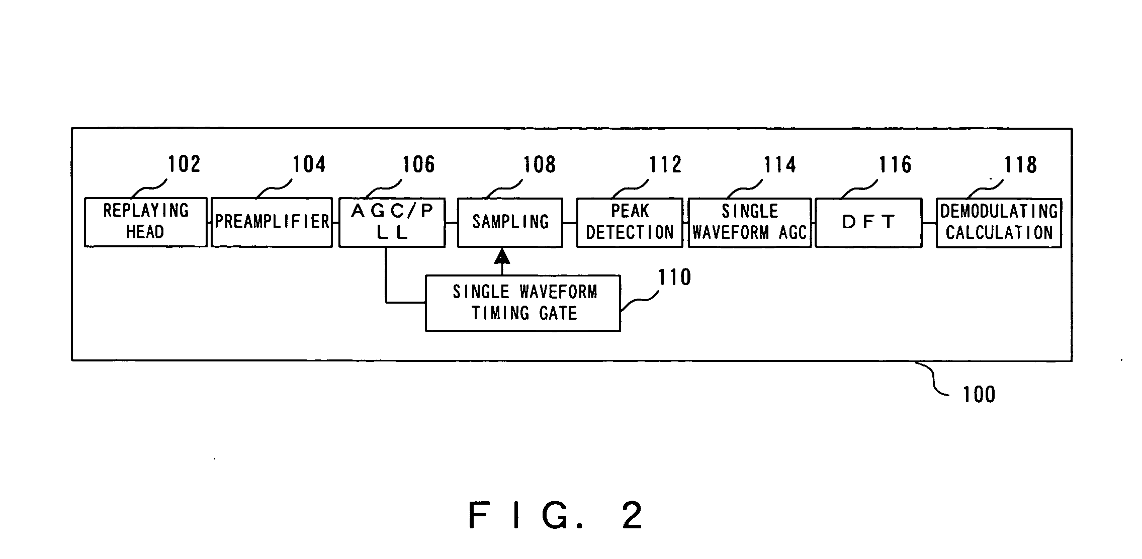
[0044]FIG. 2 shows an overview of a servo demodulating circuit 100 relating to the embodiments of the present invention.

[0045]The servo demodulating circuit 100 comprises an auto gain control means / phase-locked loop (AGC / PLL) 106, waveform sampling means 108, a single waveform timing gate 110, a peak detection means 112, single waveform AGC means 114, discrete Fourier transform (DFT) means 116, and a demodulating calculation means 118. Note that in the drawing, although a...


PUM


Abstract

Servo demodulation is performed by appropriately compensating for demodulation errors caused by fluctuation of the replayed signal amplitude of a phase servo pattern. A servo demodulating circuit comprises single waveform sampling means for reading into a register a single waveform of a servo burst signal included in a phase servo signal based on a sampling clock synchronized by clock synchronization means, single waveform digitizing means for calculating an amplitude value of the single waveform of the servo burst signal from peak and bottom of the single waveform of the servo burst signal read into the register, and for standardizing a value of the register based on an amplitude value of the single waveform of the servo burst signal, and phase information calculation means for calculating phase information of the single waveform of the servo burst signal based on the value of the register standardized by the waveform digitizing means.

Description

BACKGROUND OF THE INVENTION[0001]1. Field of the Invention[0002]The present invention relates to a servo demodulating circuit and method of a magnetic transfer medium.[0003]2. Description of the Related Art[0004]The conventional method of writing servo information (servo patterns) of a magnetic disk onto a disk operates by using a servo track writer (STW). In such a method, for example, the servo write time for a 20 Gb / disk-class magnetic disk requires approximately 10 minutes / disk. Since there has been a current trend of ever increasing track recording density in the magnetic disks, the time required for servo writing by STW has become longer, causing significant cost problems.[0005]In light of the problems with STW, a method has been proposed as a new technique for recording servo information in patterns in a master disk and storing the information by magnetic transfer.[0006]An example of the magnetic transfer method is, as described in Non-patent Document 1, a method for forming ...

Claims


Application Information

Patent Timeline
IPC IPC(8): G11B20/08G11B20/10G11B5/09
CPCG11B5/59605G11B2220/2516G11B20/10009G11B5/865
Inventor KURODA, SUMIO
Owner TOSHIBA STORAGE DEVICE CORP
Learn More