Computer-aided imaging diagnostic processing apparatus and computer-aided imaging diagnostic processing method

a diagnostic processing and computer-aided imaging technology, applied in the direction of reconstruction from projection, tomography, instruments, etc., can solve the problems of difficult to obtain the volume rendering image desired by the user, the inability to use a screening technique, and the increase in the load required for radiogram interpretation

Active Publication Date: 2007-11-29
TOSHIBA MEDICAL SYST CORP
View PDF11 Cites 24 Cited by
  • Summary
  • Abstract
  • Description
  • Claims
  • Application Information

AI Technical Summary

Benefits of technology

[0010] The present invention has been made in consideration of the above situation, and has as its object to provide a computer-aided imaging diagnostic processing apparatus and

Problems solved by technology

However, this technique could not be used for screening because it took a long imaging time before the advent of a helical scan type CT in 1990.
However, the multi-detector helical CT generates roughly thousand images per scan, and hence the load required for interpretation of radiograms greatly increases.
It is, however, difficult to obtain a volume rendering image desired by the user by using these feature amounts, and hence

Method used


Image

  • Computer-aided imaging diagnostic processing apparatus and computer-aided imaging diagnostic processing method
  • Computer-aided imaging diagnostic processing apparatus and computer-aided imaging diagnostic processing method
  • Computer-aided imaging diagnostic processing apparatus and computer-aided imaging diagnostic processing method

Examples


first embodiment

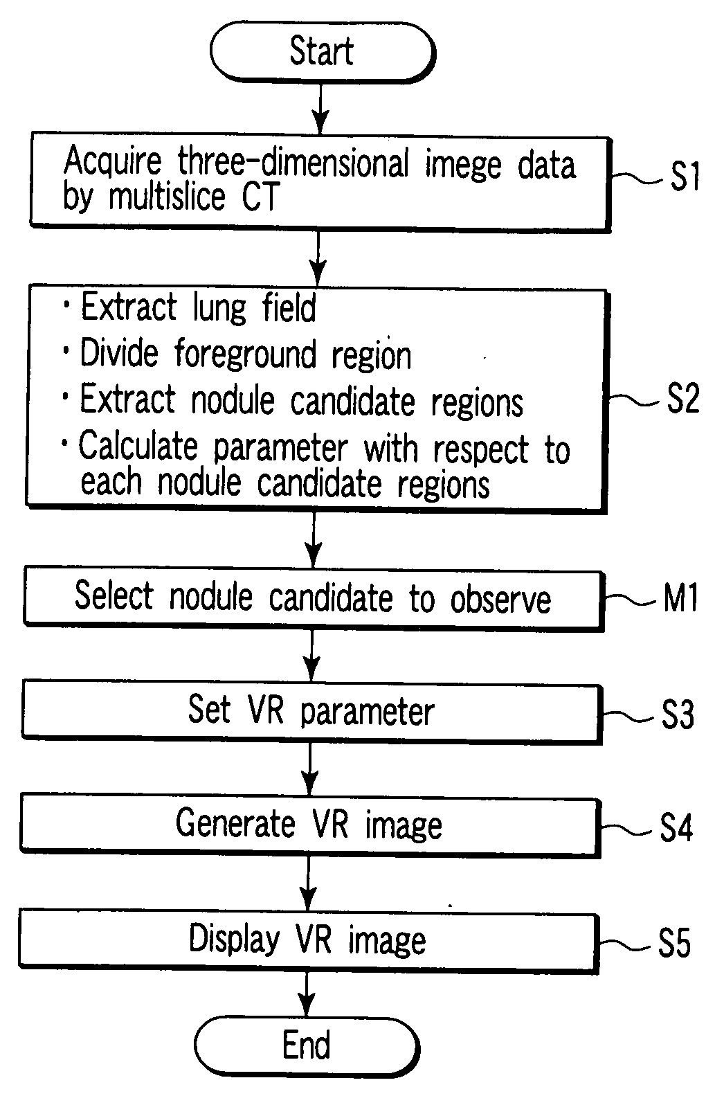
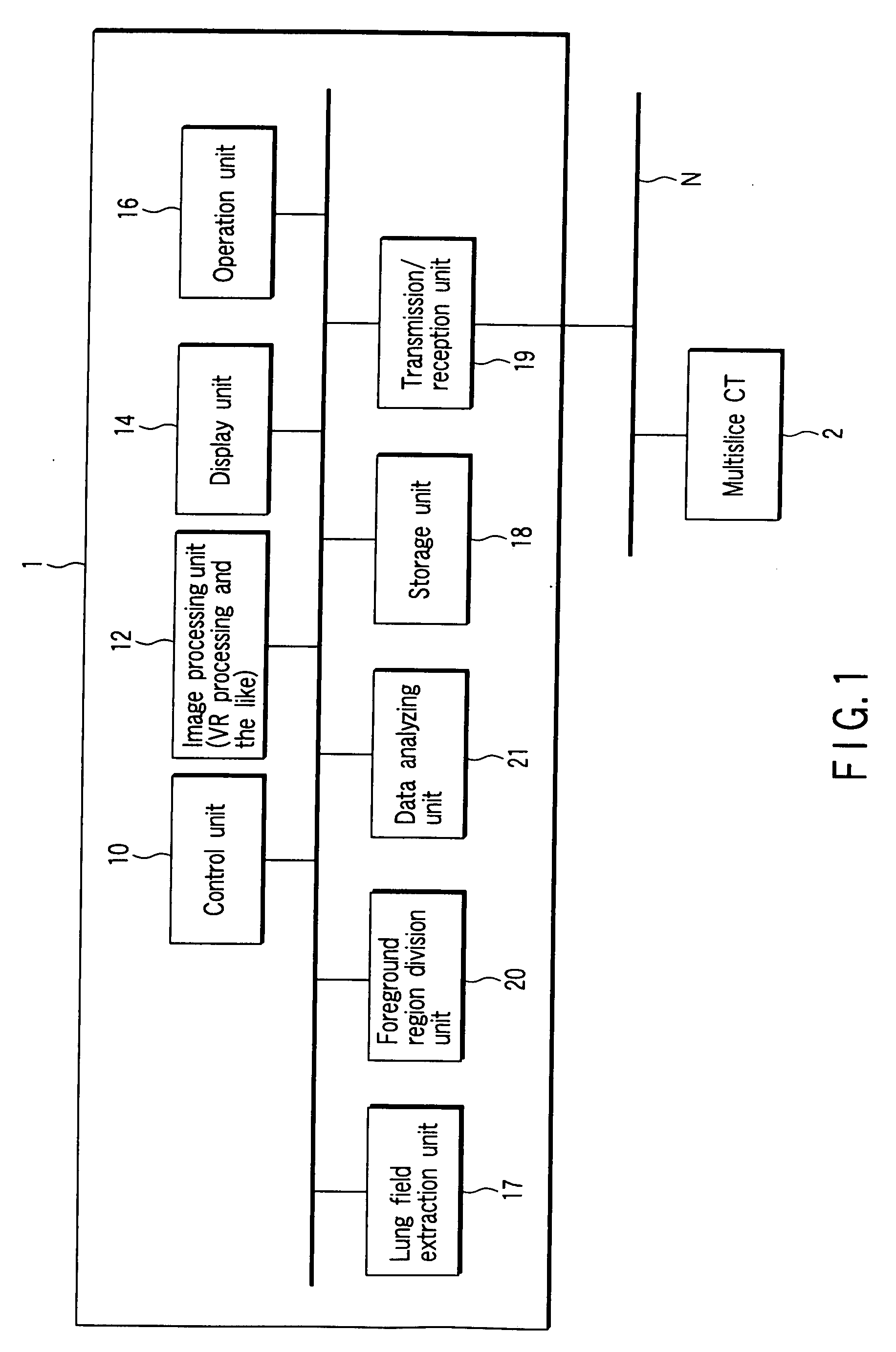
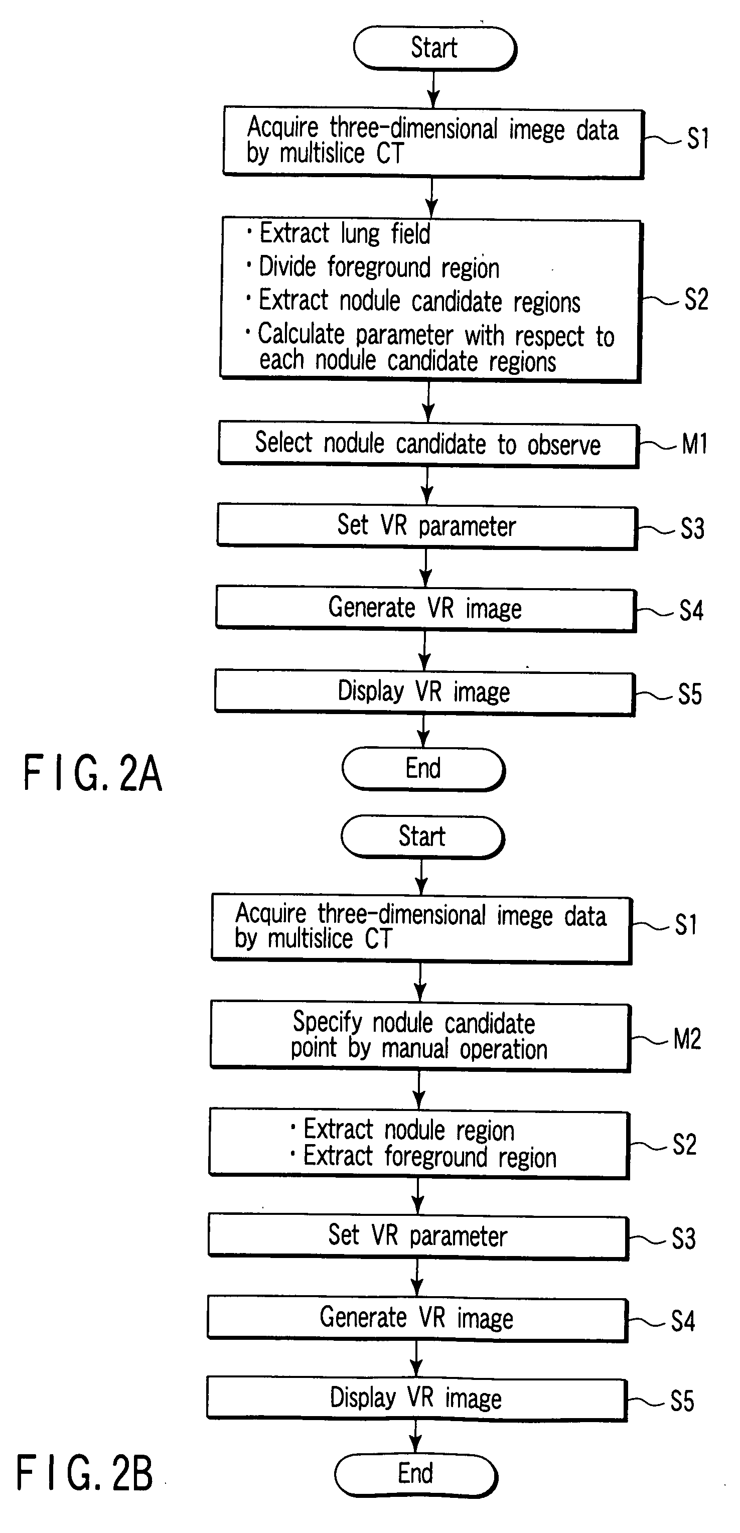
[0054]FIG. 1 is a block diagram showing the arrangement of a computer-aided imaging diagnostic processing apparatus 1 according to this embodiment. Referring to FIG. 1, the computer-aided imaging diagnostic processing apparatus 1 comprises a control unit 10, image processing unit 12, display unit 14, operation unit 16, storage unit 18, transmission / reception unit 19, lung field extraction unit 17, foreground region division unit 20, and data analyzing unit 21.

[0055] The computer-aided imaging diagnostic processing apparatus according to this embodiment can use, for example, a general-purpose computer apparatus as basic hardware. The lung field extraction unit 17 and the data analyzing unit 21 can be implemented by causing a processor mounted in the above computer apparatus to execute imaging diagnostic processing programs. In this case, it suffices to implement the computer-aided imaging diagnostic processing apparatus 1 by installing the above imaging diagnostic processing program...

first modification

(First Modification)

[0084] The above embodiment has exemplified the case wherein an opacity curve which is a linear function is set as a typical example. However, an opacity curve can be defined by a desired function or curve sketching instead of a linear function. FIG. 19 shows another typical example of the opacity curve. It is preferable from the viewpoint of operability that a desired one of preset opacity curves can be selected by using a user interface like that shown in FIG. 20.

second modification

(Second Modification)

[0085] Performing predetermined operation makes it possible to change the VR parameter (opacity curve) set in accordance with the above embodiment to another setting. The contents of this operation will be described below with reference to a case wherein an opacity curve is a linear function.

[0086] An opacity curve as a linear function can be changed in accordance with two condition settings. One setting is the gradient of an opacity curve, and the other setting is the H.U. value which makes opacity=0.

[0087] FIGS. 21 to 24 each show an opacity curve having a gradient S1-1 and the VR image generated by using the opacity curve, which are obtained when the H.U. value which makes opacity=0 is changed every 100 [H.U.] (note, however, that the H.U. value is changed in units of 300 [H.U.] in the cases shown in FIGS. 23 and 24). In the case shown in FIG. 21 (the lower limit of the opacity is −750 [H.U.] with the gradient S1-1), many blood vessels around a nodule are d...


PUM


Abstract

In consideration of the fact that a lung field varies in the density of sponge-like tissue depending on an individual or display region, an opacity curve which gives priority to a nodule candidate region or an extended nodule candidate region can be set by generating a histogram concerning a volume of interest which includes a foreground region, and using the statistical analysis result on the histogram as an objective index.

Description

CROSS-REFERENCE TO RELATED APPLICATIONS [0001] This application is based upon and claims the benefit of priority from prior Japanese Patent Application No. 2006-148108, filed May 29, 2006, the entire contents of which are incorporated herein by reference. BACKGROUND OF THE INVENTION [0002] 1. Field of the Invention [0003] The present invention relates to a computer-aided imaging diagnostic processing apparatus and computer-aided imaging diagnostic processing method which can satisfactorily visualize a desired target by properly setting parameters in volume rendering (VR) processing. [0004] 2. Description of the Related Art [0005] Currently, in Japan, lung cancer has become the first cause of malignant tumor death and has increased steadily. This leads to strong social demands for not only prevention by anti-smoking measures but also early detection. In Japan, each municipality has practiced lung cancer screening by plain chest radiograph and sputum cytology. A 1998 report by “Study ...

Claims


Application Information

Patent Timeline
IPC IPC(8): G06K9/00G06K9/34G06T15/08
CPCA61B6/032G06T15/08G06T11/008A61B6/4085
Inventor SUGIYAMA, ATSUKOYAMAGATA, HITOSHIOHYU, SHIGEHARU
Owner TOSHIBA MEDICAL SYST CORP
Why Eureka
Try Eureka