Passive optical network rogue optical network unit diagnostics

Active Publication Date: 2007-11-29
ALCATEL LUCENT SAS
View PDF3 Cites 33 Cited by
  • Summary
  • Abstract
  • Description
  • Claims
  • Application Information

AI Technical Summary

Benefits of technology

[0012]A major advantage of the present invention is automated determination of problematic ONUs without taking manual diagnostic measures on the PON.
[0013]In one embodiment of the present invention, a method for passive optical network rogue optical network unit diagnostics, comprises, detecting an alarm of a network, correlating the detected alarm to a bandwidth map, and selectively disabling an optical network unit next to the alarming ONU on the bandwidth map for a pre-determined interval. The method may also comprise collecting bandwidth mapping information, creating the bandwidth map and determining an optical network unit proximate to the detected alarm based upon the upstream bandwidth map. The method may additionally comprise verifying the number of detected alarms during the pre-determined interval. The ONU is flagged as a possible rogue ONU and disabled if there is a reduction in detected alarms during the pre-determined interval. In order to confirm the ONU is indeed rogue, the ONU will be re-enabled to verify that the number of alarms increases. If the number of alarms increases, the ONU is permanently disabled—wherein the alarm may be detected at the OLT and wherein the alarm may be detected at the ONU.
[0014]In a further embodiment of the present invention, a computer readable medium comprises instructions for, sequentially disabling an optical network unit on a bandwidth map proximate to an alarming optical network unit for a pre-determined interval, observing alarm information for the pre-determined interval, and listing as rogue the sequentially disabled optical network unit if the observation indicates a reduction in the number of alarms during the pre-determined interval. The computer readable medium may also comprise, enabling rogue listed optical network units, monitoring alarm information during the enablement of the rogue listed network units and acquiring the number and type of observed alarms during the pre-determined interval to determine probable rogue optical network units. The computer readable medium may additionally comprise analyzing the observed alarms to determine probable rogue optical network units.
[0015]In yet a further embodiment, a system of passive optical network rogue optical network unit diagnostics, comprises, a memory that receives at least one of, an alarm information and a bandwidth map, and a processor communicably coupled to the memory, wherein the processor, gathers the alarm information of an alarming optical network unit, correlates the gathered alarm information to the bandwidth map, disables an optical network unit upstream to the alarming optical network unit on the bandwidth map for a pre-determined interval, and observes a subsequent alarm information for the pre-determined interval. The system may also comprise an optical transmitter coupled to the processor, an optical receiver coupled to the processor and an optical transceiver coupled to the processor.

Problems solved by technology

A rogue ONU on a PON can cause other ONUs on the PON to exhibit problematic behavior in the form of alarms such as, Bit Interleaved Parity (BIP), Bit Error Rate (BER), and re-ranging.
A rogue ONU may be causing timeslot violations, it could have a laser mis-calibrated, a laser continuously on, or a laser that intermittently fails to come on.
It is difficult to identify a rogue ONU without manually interacting with that ONU on the PON.
Manual troubleshooting is insufficient in a customer site / field situation and is tedious in in-house lab scenarios.

Method used


Image

  • Passive optical network rogue optical network unit diagnostics
  • Passive optical network rogue optical network unit diagnostics
  • Passive optical network rogue optical network unit diagnostics

Examples


Embodiment Construction

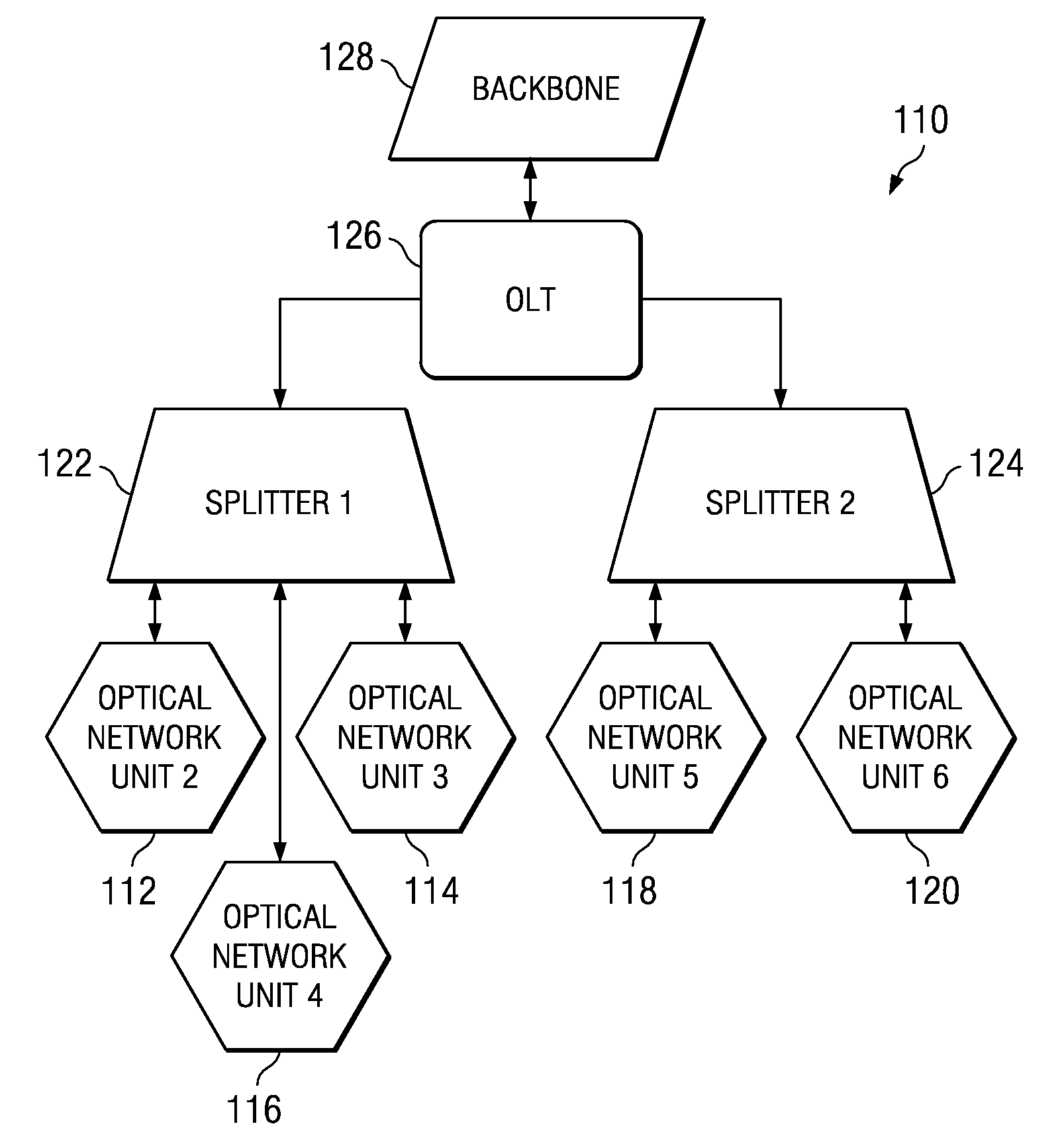
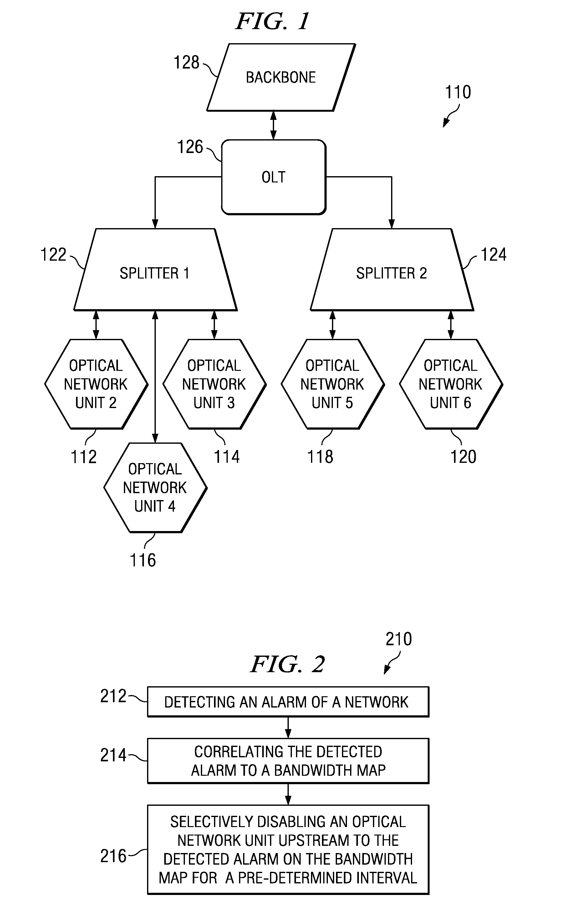
[0023]Referring now to FIG. 1, a network is shown in which the optical network terminations 112, 114, 116, 118, 120 branch out through splitters 122, 124 from an optical line termination 126 which is connected to the network backbone 128. The optical line termination is connected to the central backbone of the network.

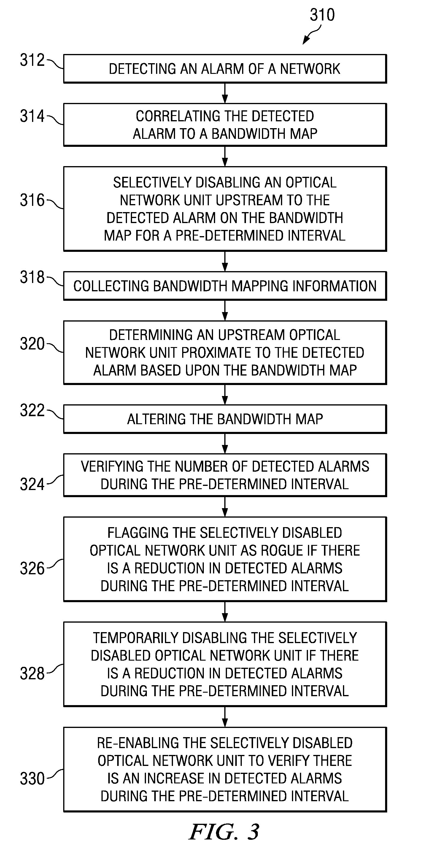
[0024]Referring now to FIG. 2, a first method of passive optical network rogue optical network unit diagnostics 210 is depicted and comprises a number of blocks or modules that are software, hardware, or firmware, and / or the combination of software, hardware, and / or firmware. A method for passive optical network rogue optical network unit diagnostics comprises, detecting 212 an alarm of a network, correlating 214 the detected alarm to a bandwidth map, and selectively disabling 216 an optical network unit proximate to the alarming ONU on the bandwidth map for a pre-determined interval. The transfer of information between the modules occurs via at least one of: a wireles...


PUM


Abstract

A system, method, and computer readable medium for passive optical network rogue optical network unit diagnostics, comprises, detecting an alarm of a network, correlating the detected alarm to a bandwidth map, and selectively disabling an optical network unit upstream to the detected alarm on the bandwidth map for a pre-determined interval.

Description

CROSS REFERENCE TO RELATED APPLICATIONS[0001]The present patent application is related to and claims the benefit of provisional patent application No. US60 / 803,317 filed on May 26, 2006, entitled PON ROGUE ONU DIAGNOSTICS, the entire contents of which are incorporated by reference herein.BACKGROUND OF THE INVENTION[0002]The present invention is generally related to optical network alarm diagnostics and, more specifically to passive optical network rogue optical network unit diagnostics.[0003]A Passive Optical Network (PON) consists of an Optical Line Termination (OLT), which resides in a Central Office (CO). The optical line termination services a number of Optical Network Units (ONUs) typically connected in a star arrangement using optical splitters, which reside at a premise of a user. Passive optical networks are designed on the premise of time-sharing of resources. The upstream data on the passive optical network sent from the optical network units to the optical line terminatio...

Claims


Application Information

Patent Timeline
IPC IPC(8): H04J14/00
CPCH04J3/14H04J3/1694H04L41/0631H04J2203/0062H04J2203/006
Inventor FERGUSON, JULIA GAYHOLLAND, THOMAS MICHAELSU, BILLY CHI-KANG
Owner ALCATEL LUCENT SAS
Why Eureka
Try Eureka