Method for casting a component and a component comprising at least partly of fibre-reinforced plastic laminate

a technology of fibre reinforced plastics and casting methods, which is applied in the direction of machines/engines, other domestic objects, transportation and packaging, etc., can solve the problems of air trapped in the laminate, method failure, air trapped, etc., and achieve the effect of reducing or eliminating the risk of air inclusion

Active Publication Date: 2007-11-29
SIEMENS GAMESA RENEWABLE ENERGY AS
View PDF4 Cites 21 Cited by
  • Summary
  • Abstract
  • Description
  • Claims
  • Application Information

AI Technical Summary

Benefits of technology

[0013]It is thus an aim of the invention to disclose a method for casting components which reduces or eliminates the risk of air inclusions in the components manufactured as composite laminates in particular fibre-reinforced plastic laminates without the disadvantages of the known methods. It is a further aim of the invention to disclose a component with at least reduced air inclusions.
[0016]The method of venting trapped air through ducts placed inside the laminate has several great advantages compared with known methods.
[0018]By ensuring venting inside the laminate, requiring only one or a few external breather locations for even very large structures the surface finishing requirements can be greatly reduced.
[0021]As a result large components for example windmill rotor blades can easily be manufacture in one piece and without any or large air inclusions.
[0027]Preferred at least two venting ducts are placed parallel and spaced. Since a venting duct with a semipermeable or resinophobic external surface essentially represents a delamination risk inside the plastic laminate, the application as a series of parallel ducts placed with some distance is of great advantage. This limits the effects of local delamination and minimises the risk of a large delamination of structural consequence.

Problems solved by technology

Such methods are used to produce fibre-reinforced plastic laminates where hand lay-up or filament winding is undesirable.
In most of such methods it can be a problem that air can get trapped in the laminate.
Air may be trapped in high points due to buoyancy, but it may also be trapped in parts of the laminate where gravity would be expected to assist in the replacement of the air with the matrix material.
This method does not work, however, when manufacturing large structures with partially or completely closed spaces that cannot be accessed during manufacturing.
Whilst this method can extend the active area of a suction vent, the effect cannot be ensured if one does not know the location of air inclusions.
Furthermore, if the vent is placed on an external surface it requires substantial finishing works after moulded.
This method will remove air from the laminate surface irrespective of where entrapment occurs, but it has the great disadvantage that if the mould surface is on the up side and the vacuum bag surface is on the down side, there is still a large risk of air inclusions close to the surface next to the mould.
The method described in EP 1 181 149 also has the disadvantage that it requires the entire surface of one side of the laminate to be covered by costly supplementary materials such as flow-assisting vacuum bags or semi-permeable membranes.
Furthermore, for elongated, partially closed structures the removal of the supplementary materials after curing of the laminate may be difficult or impossible, and the supplementary materials may need to be left in place, which in turn could lead to problems over time with accumulation of condensation etc. in voids between the supplementary materials and the laminate.

Method used


Image

  • Method for casting a component and a component comprising at least partly of fibre-reinforced plastic laminate
  • Method for casting a component and a component comprising at least partly of fibre-reinforced plastic laminate
  • Method for casting a component and a component comprising at least partly of fibre-reinforced plastic laminate

Examples


Embodiment Construction

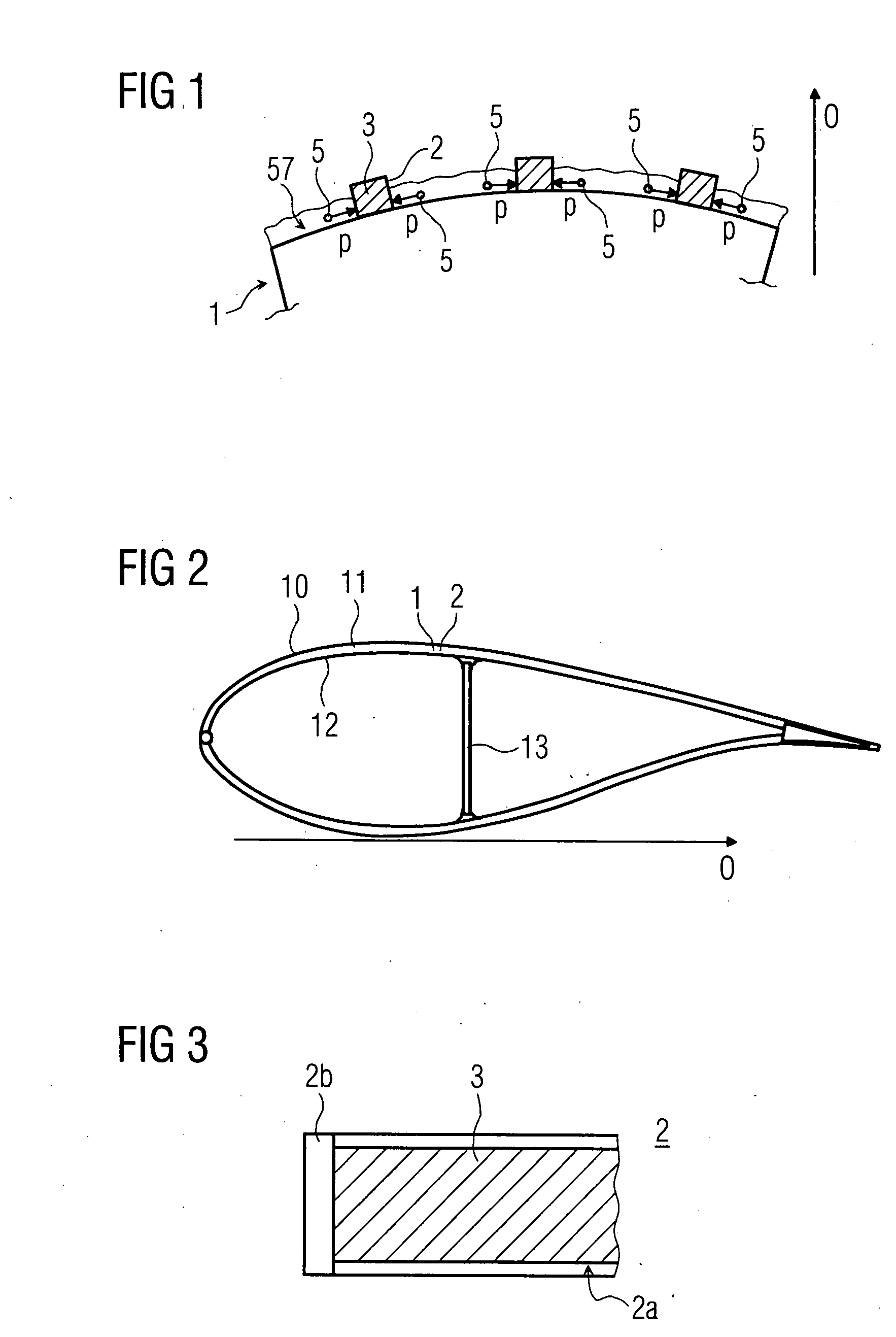
[0038]FIG. 1 shows schematically an embodiment of the fibre-reinforcement 1. Inside the fibre-reinforcement 1 several venting ducts 2 are laid up. The venting duct comprises a breather filter 3. During the casting process the fibre-reinforcement 1 is wetted by the plastic laminate 57. Now air inclusions 5 arise by for example, different curing of the plastic laminate 57. By the invention the air 5 passes, indicated in FIG. 1 with p, through the outer surface of the venting ducts 2. The air is now inside the venting duct 2 that is in the breather filter 3. As a result of the material of the venting ducts 2 only the air is allow to pass through. The plastic laminate 57 itself can not pass through. Therefore the air is leaded by the breather filter 3 inside the venting ducts 2 to the outside. This is shown by the arrow o. Hence, the air in the air inclusions 5 can discharge by the venting ducts 2. By this air inclusions are eliminated or reduced.

[0039]FIG. 3 shows schematically an embo...


PUM

PropertyMeasurementUnit
widthaaaaaaaaaa
semi-permeableaaaaaaaaaa
wettingaaaaaaaaaa

Abstract

There is described a method for casting a component comprising at least partly of fibre-reinforced plastic laminate by which the fibre-reinforcement is arranged in a casting mould, wherein at least one venting duct is placed, wherein said fibre-reinforcement and said venting duct are at least partly wetted by the plastic during the casting process in such a way that venting is achieved through said venting duct, and wherein the surface of the venting duct is at least partially made with a semi-permeable membrane that allows the passage of gases but does not allow or only slowly allows the passage of plastics. Furthermore there is described a component comprising at least partly of fibre-reinforced plastic laminate, wherein the plastic laminate inside comprises of one or more venting ducts, wherein the surface of a venting duct is at least partially made with a semi-permeable membrane that allows the passage of gases but does not allow or only slowly allows the passage of plastics.

Description

CROSS REFERENCE TO RELATED APPLICATIONS[0001]This application claims priority of European application No. 06010921.2 EP filed May 26, 2006, which is incorporated by reference herein in its entirety.FIELD OF INVENTION[0002]The invention relates to a method for casting a component comprising at least partly of fibre-reinforced plastic laminate wherein the fibre-reinforcement is at least partly wetted by the plastic laminate, as well as to a component comprising at least partly of fibre-reinforced plastic laminate.BACKGROUND OF INVENTION[0003]Such methods are used to produce fibre-reinforced plastic laminates where hand lay-up or filament winding is undesirable. The fibre reinforcement can be of any known type, such as chop stand or woven fabric mats, multi-axis interlaid scrims, warp-thread reinforced unidirectional performs, single or joined roving bundles, and of any known material, such as glass, Kevlar, carbon or hemp. The fibre reinforcement may be supplemented with pre-fabricate...

Claims


Application Information

Patent Timeline
Patent Type & Authority Applications(United States)
IPC IPC(8): B32B27/08
CPCB29C70/443Y10T428/1352B29L2031/08B29C70/547
Inventor STIESDAL, HENRIK
Owner SIEMENS GAMESA RENEWABLE ENERGY AS
Why Eureka
Try Eureka