Adhesive tape and method of use

a technology of adhesive tape and adhesive layer, applied in the field of adhesive tape, can solve the problems of staining of the adhesive layer and reduced adhesion ability, and achieve the effect of improving adhesion ability and preventing the formation of stain on the adhesive layer

Active Publication Date: 2007-11-29
HONDA MOTOR CO LTD
View PDF1 Cites 1 Cited by
  • Summary
  • Abstract
  • Description
  • Claims
  • Application Information

AI Technical Summary

Benefits of technology

[0008]In order to achieve the above object, according to a first feature of the present invention, there is provided an adhesive tape comprising a tape body having an adhesive layer on one side, and a release paper for protecting the adhesive layer of the tape body. The release paper is laminated on the tape body. The tape body includes a tape center portion to be affixed to an object, and a tape outer periphery portion continuous to an outer periphery of the tape center portion so that the tape outer periphery portion can be separated therefrom. In addition, the release paper includes a release paper center portion laminated on the tape center portion except at least a part of the outer periphery of the tape center portion, and a release paper outer periphery portion at least partially continuous to an outer periphery of the release paper center portion so that the release paper center portion can be separated therefrom.
[0009]With this arrangement, the tape body comprises the tape center portion to be affixed to the object, and the tape outer periphery portion separatably continuous to the outer periphery of the tape center portion; and the release paper comprises the release paper center portion laminated on the tape center portion except at least a part of the outer periphery of the tape center portion, and the release paper outer periphery portion at least partially continuous to the outer periphery of the release paper center portion. Thus, even if the release paper center portion is separated from the tape center portion, the tape center portion adheres to the release paper outer periphery portion at a part of the outer periphery and is retained integrally with the release paper outer periphery portion. Therefore, after a part of the tape center portion, whose adhesive layer is exposed at such a part, is affixed to the object while holding the tape outer periphery portion and the release paper outer periphery portion with fingers, then the tape outer periphery portion and the release paper outer periphery portion are separated from the tape center portion, and a part of the outer periphery of the tape center portion is affixed to the object, thereby completing the adhesion operation. In this process, since there is no need to touch the adhesive layer of the tape center portion with fingers, formation of a stain on the adhesive layer is prevented and its adhesion ability is improved. Moreover, clean finishing of the adhered portion is ensured.

Problems solved by technology

However, in this conventional art, a user is required to pinch the adhesive layer of the adhesive plaster body when removing the adhesive plaster body remaining on the other half of the release paper, leading to a possibility that the adhesive layer is stained and its adhesion ability is reduced.

Method used


Image

  • Adhesive tape and method of use
  • Adhesive tape and method of use
  • Adhesive tape and method of use

Examples


first embodiment

[0034]the present invention will be described below with reference to FIGS. 1 to 6B.

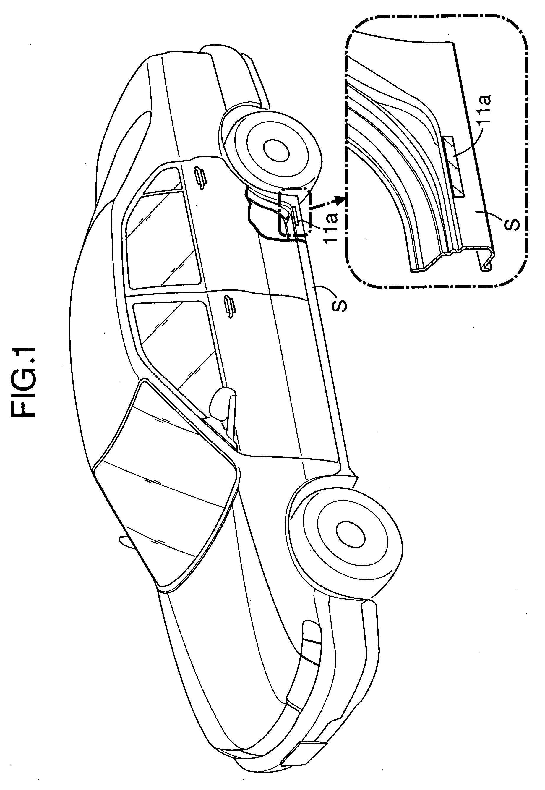
[0035]As shown in FIG. 1, a tape (a tape center portion 11a which will be described later) is affixed to a side face of a side sill S of an automobile in order to prevent damage to a painted surface by a stone or the like hitting thereon after being splashed up by a front wheel.

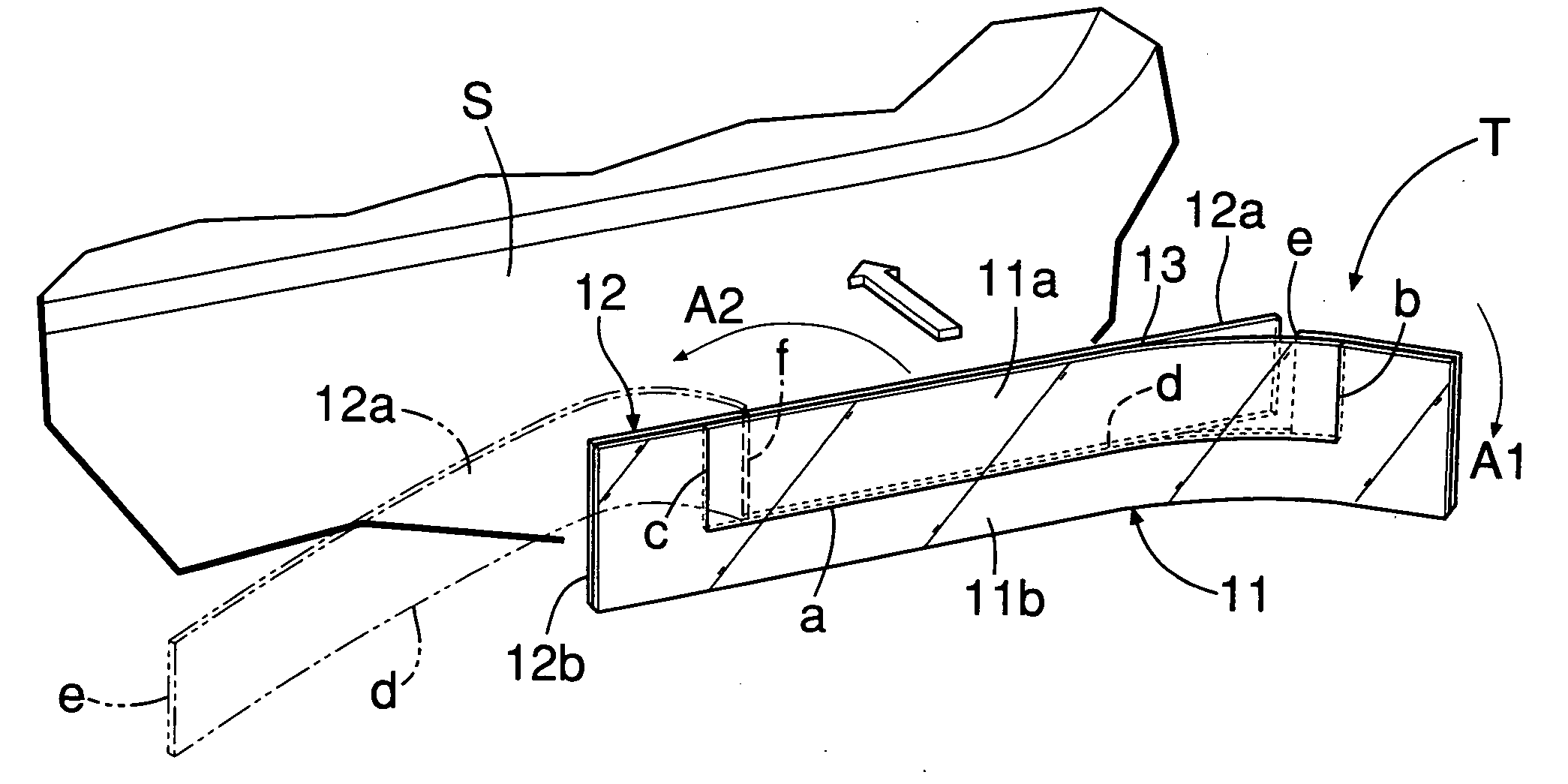
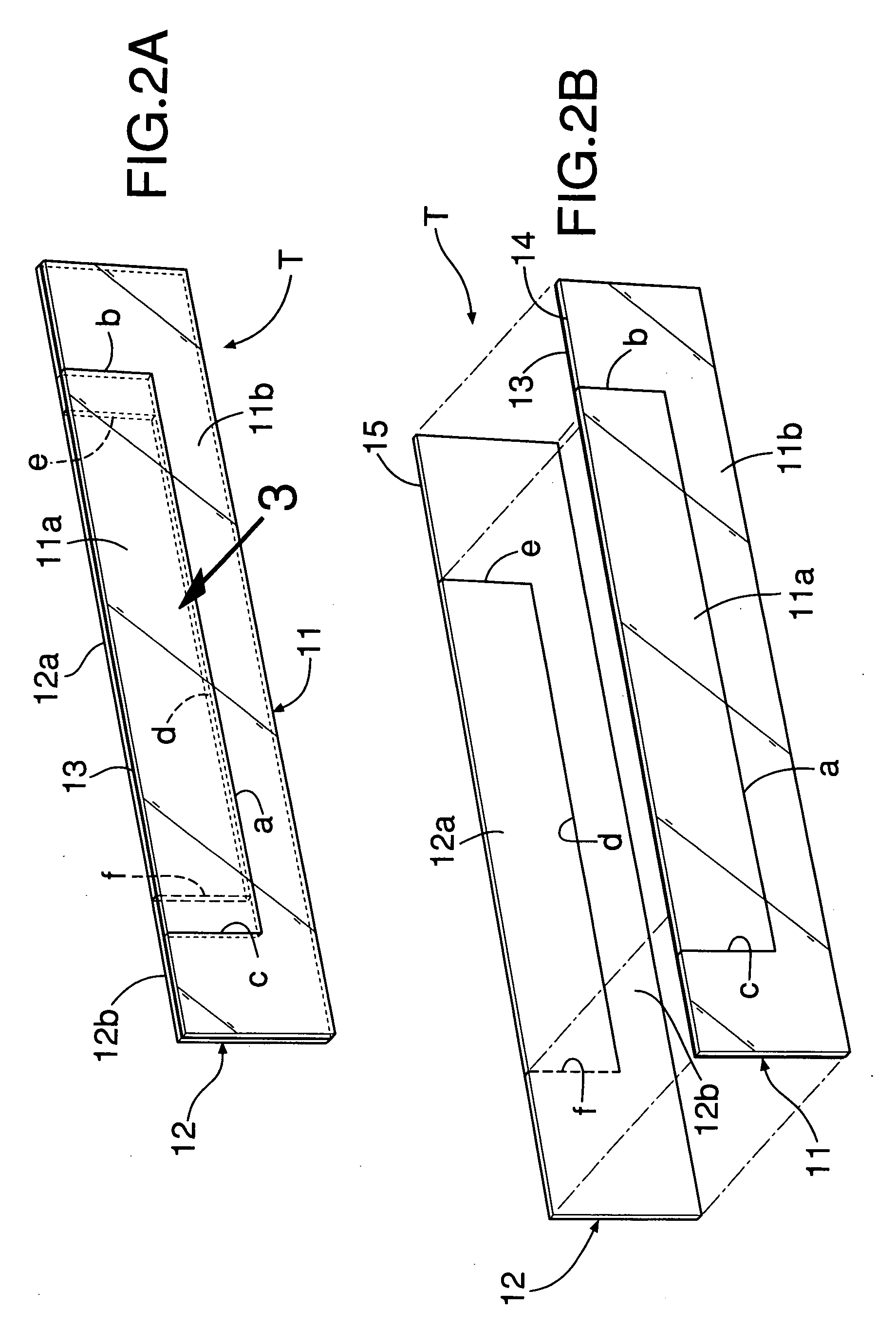
[0036]As shown in FIGS. 2A, 2B and 3, an adhesive tape T including the tape center portion 11a comprises a tape body 11 made of a synthetic resin on which an adhesive layer 13 is formed on one side, and a release paper 12 of the same dimension laminated on the tape body 11 so as to protect the adhesive layer 13 of the tape body 11. The release paper 12 is subjected to a surface treatment so that the adhesive layer 13 of the tape body 11 is difficult to adhere to the release paper 12. Therefore, the tape body 11 lightly adheres to the release paper 12 so that although they are joined to each other, the release paper 12 can be e...

second embodiment

[0048]In a second embodiment shown in FIG. 7A, the slit c of the tape body 11 is repositioned so as to overlie the perforated line f of the release paper 12, which remains in its previous position. Even with this arrangement, there is no fear that the tape center portion 11a drops off when the release paper center portion 12a is separated from the tape center portion 11a, because one end of the tape center portion 11a is affixed to the release paper outer periphery portion 12b (see the shaded portion).

[0049]In the first and second embodiments, the tape center portion 11a is formed along the upper edge of the tape body 11, but in a third embodiment shown in FIG. 7B, the tape center portion 11a is spaced apart from the peripheral edges of the tape body 11 and is formed entirely inside the peripheral edges. Also, in a fourth embodiment shown in FIG. 7C, the tape center portion 11a has semi-spherical shaped opposite ends formed by rounding the opposite ends of the rectangular-shaped tap...


PUM

PropertyMeasurementUnit
L-shapeaaaaaaaaaa
rectangular shapeaaaaaaaaaa
adhesiveaaaaaaaaaa

Abstract

A tape body having an adhesive layer includes a tape center to be affixed to an object and a tape outer periphery continuous to an outer periphery of the tape center and separable therefrom. A release paper includes a release paper center laminated on the tape center except at the outer periphery of the tape center, and a release paper outer periphery at least partially continuous to an outer periphery of the release paper center and separable therefrom. Thus, when the release paper center is separated from the tape center, opposite ends of the tape center adhere to the release paper outer periphery. Therefore, after a part of the tape center is affixed to the object, the tape outer periphery and the release paper outer periphery are separated from the tape center, and the remaining parts of the tape center are affixed to the object, thereby completing the adhesion operation.

Description

CROSS-REFERENCE TO RELATED APPLICATIONS[0001]The present invention claims priority under 35 USC 119 based on Japanese patent application No. 2006-146309, filed on May 26, 2006. The entirety of the subject matter of this priority document is incorporated by reference herein.BACKGROUND OF THE INVENTION[0002]1. Field of the Invention[0003]The present invention relates to an adhesive tape comprising a tape body having an adhesive layer on one side, and a release paper for protecting the adhesive layer of the tape body, the release paper being laminated on the tape body.[0004]2. Description of the Related Art[0005]Japanese Patent Application Laid-open No. 5-92022 discloses an adhesive plaster comprising a large number of adhesive plaster bodies arranged on a band-shaped (elongate rectangular shaped) release paper (separation paper) at predetermined intervals, the release paper being longitudinally bisected by a cut (slit) in order to facilitate removal of each adhesive plaster body. The ...

Claims


Application Information

Patent Timeline
Patent Type & Authority Applications(United States)
IPC IPC(8): B32B33/00C09J7/20
CPCC09J7/02C09J7/0232C09J2201/28B60R19/42Y10T428/15Y10T428/1495Y10T428/1486Y10T428/149Y10T428/14C09J7/20C09J7/403C09J2301/204
Inventor SAKAI, HIROYUKI
Owner HONDA MOTOR CO LTD
Why Eureka
Try Eureka